RF3000 データシートの表示(PDF) - RF Micro Devices
部品番号
コンポーネント説明
一致するリスト
RF3000 Datasheet PDF : 28 Pages
| |||
RF3000
The RF3000 signals that it is nearing the end of the preamble and header transmission by driving TX RDY high. This sig-
nals the user that transmission data clocks are coming. When the RF3000 is ready to transmit data it will begin clocking
transmit data. Data to be transmitted should be present on TX DATA on the rising edge of DATA CLK. The RF3000 will
only clock in the number of data-bits to fill the specified transmission time.
IEEE802.11b DSSS Transmission Summary
1. TX Mode different:
Write value to the mode register according to table.
2. TX Length different:
Write the number of uS to transmit in the TX length registers.
3. Drive TX PE High and wait for TX RDY to go High.
4. Transmit data must be valid on the rising edge of DATA CLK.
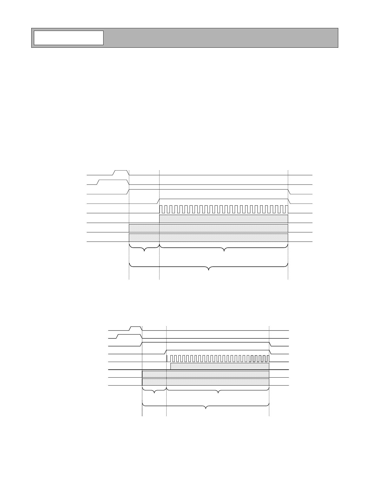
Figure 8 shows the primary interface mode for the RF3000 TX Data port.
CCA
RX PE
TX PE
TX RDY
DATA CLK
TX DATA
TX I
TX Q
Preamble
and Header
Data
Rate Determined from Control Port Register 1
Figure 8. IEEE802.11b Transmit Timing Overview
The RF3000 has provision for an alternate Transmit Data port interface. In the transmit interface an extra clock is
asserted after TXRDY goes ‘high' and before the first TX data clock on DATA CLK, see Figure 8a. The alternate Transmit
interface is enabled by writing 0x08 into RF3000 Register 0x1C.
CCA
RX PE
TX PE
TX RDY
DATA CLK
TX DATA
TX I
TX Q
Preamble and
Header
Data
Rate Determined from Control Port Register 1
Figure 8a. Alternate Transmit Interface
11-332
Rev A4 031216
Share Link: 