HIP1011D データシートの表示(PDF) - Intersil
部品番号
コンポーネント説明
一致するリスト
HIP1011D Datasheet PDF : 15 Pages
| |||
HIP1011D, HIP1011E
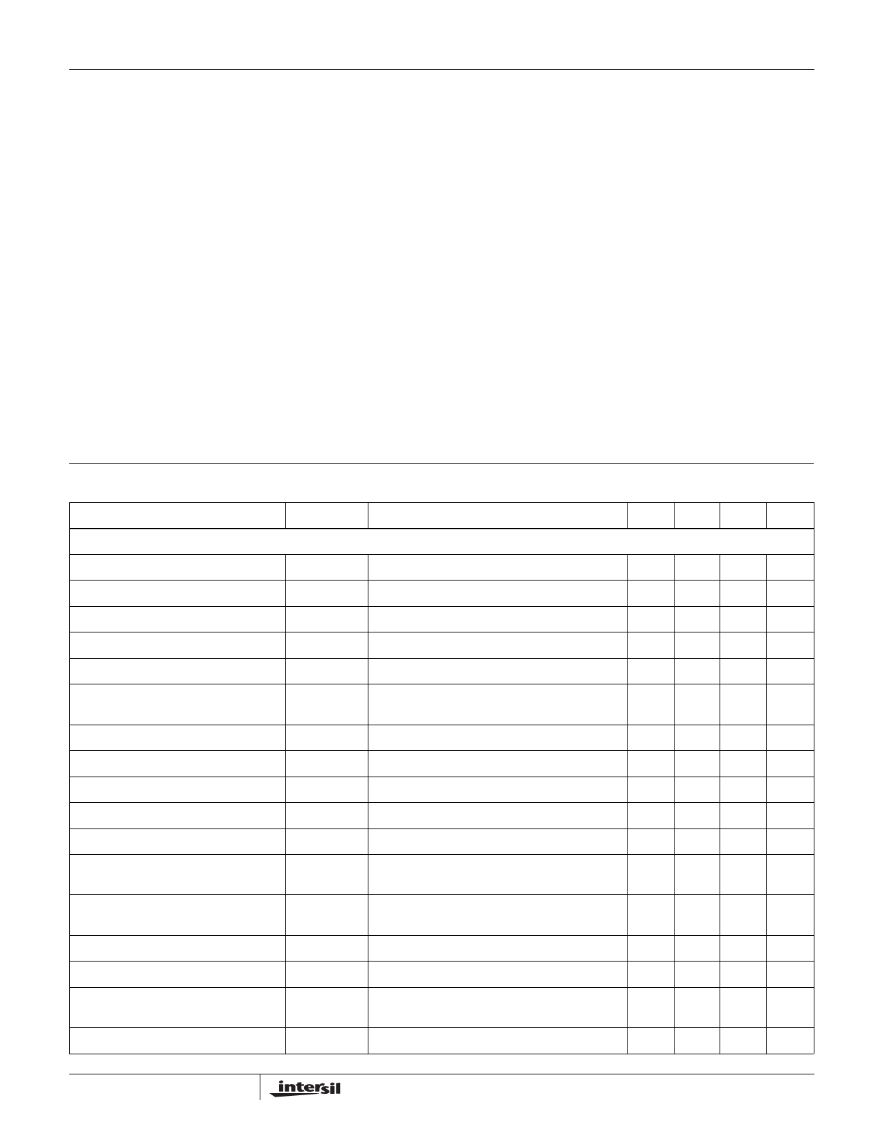
Absolute Maximum Ratings
12VIN . . . . . . . . . . . . . . . . . . . . . . . . . . . . . . . . . . . . -0.5V to +14.0V
12VO, 12VG, 3V5VG . . . . . . . . . . . . . . . . . . . . -0.5V to 12VIN+0.5V
M12VIN . . . . . . . . . . . . . . . . . . . . . . . . . . . . . . . . . . -14.0V to +0.5V
M12VO, M12VG. . . . . . . . . . . . . . . . . . . . . . VM12VIN-0.5V to +0.5V
3VISEN, 5VISEN . . . . . . . . . . -0.5V to the Lesser of 12VIN or +7.0V
Voltage, Any Other Pin. . . . . . . . . . . . . . . . . . . . . . . . -0.5V to +7.0V
12VO Output Current . . . . . . . . . . . . . . . . . . . . . . . . . . . . . . . . . . .3A
M12VO Output Current . . . . . . . . . . . . . . . . . . . . . . . . . . . . . . . 0.8A
ESD Classification . . . . . . . . . . . . . . . . . . . . . . . . . . . . . 2KeV (HBM)
Thermal Information
Thermal Resistance (Typical, Note 1)
θJA (°C/W)
SSOP Package . . . . . . . . . . . . . . . . . . . . . . . . . . . .
77
Maximum Junction Temperature . . . . . . . . . . . . . . . . . . . . . . . 150°C
Maximum Storage Temperature Range . . . . . . . . . . . -65°C to 150°C
Maximum Lead Temperature (Soldering 10s) . . . . . . . . . . . . . 300°C
(SSOP - Lead Tips Only)
Operating Conditions
12VIN Supply Voltage Range . . . . . . . . . . . . . . . . +10.8V to +13.2V
5V and 3.3V Input Supply Tolerances. . . . . . . . . . . . . . . . . . . . . . ±10%
12VO Output Current . . . . . . . . . . . . . . . . . . . . . . . . . . . . .0 to +0.5A
M12VO Output Current . . . . . . . . . . . . . . . . . . . . . . . . . . .0 to +0.1A
Temperature Range (TA) . . . . . . . . . . . . . . . . . . . . . . . . 0°C to 70°C
CAUTION: Stresses above those listed in “Absolute Maximum Ratings” may cause permanent damage to the device. This is a stress only rating and operation of the
device at these or any other conditions above those indicated in the operational sections of this specification is not implied.
NOTES:
1. θJA is measured with the component mounted on a high effective thermal conductivity test board in free air. See Tech Brief TB379 for details.
2. All voltages are relative to GND, unless otherwise specified.
Electrical Specifications
PARAMETER
Nominal 5.0V and 3.3V Input Supply Voltages,
12VIN = 12V, M12VIN = -12V, TA = TJ = 0 to 70°C, Unless Otherwise Specified
SYMBOL
TEST CONDITIONS
MIN
5V/3.3V SUPPLY CONTROL
5V Overcurrent Threshold
5V Overcurrent Threshold Voltage
5V Overcurrent Threshold Voltage
5V Undervoltage Trip Threshold
5V Undervoltage Fault Response Time
5V Turn-On Time
(PWRON High to 5VOUT = 4.75V)
IOC5V
VOC5V_1
VOC5V_2
V5VUV
t5VUV
tON5V
See Figure 24, Typical Application
VOCSET = 0.6V
VOCSET = 1.2V
(HIP1011D only)
(HIP1011D only)
C3V5VG = 0.022µF, C5VOUT = 2000µF, RL = 1Ω
-
33
70
4.42
-
-
3V Overcurrent Threshold
IOC3V
See Figure 24, Typical Application
-
3V Overcurrent Threshold Voltage
VOC3V_1 VOCSET = 0.6V
41
3V Overcurrent Threshold Voltage
VOC3V_2 VOCSET = 1.2V
89
3V Undervoltage Trip Threshold
V3VUV
(HIP1011D Only)
2.74
3V Undervoltage Fault Response Time
t3VUV
(HIP1011D Only)
-
3V5VG Undervoltage Enable Threshold V3V5VGENVth (HIP1011D Only)
-
Voltage
3V Turn-On Time
(PWRON High to 3VOUT = 3.00V)
3V5VG VOUT High
Gate Output Charge Current
Gate Turn-On Time
(PWRON High to 3V5VG = 11V)
tON3V
C3V5VG = 0.022µF, C3VOUT = 2000µF,
-
RL = 0.43Ω
Vout_hi_35VG PWRON = High, FLTN = High
11.5
IC3V5VG PWRON = High, V3V+5VG = 4V
19
tON3V5V C3V5VG = 0.033µF, 3V5VG Rising 10% to 90%
-
Gate Turn-Off Time
tOFF3V5V C3V5VG = 0.033µF, 3V5VG Falling 90% to 10%
-
TYP
8
42
80
4.65
110
6.5
10
52
98
2.86
110
9.6
6.5
11.8
25.0
280
2
MAX UNITS
-
A
50
mV
90
mV
4.8
V
160
ns
-
ms
-
A
62
mV
108 mV
2.98
V
160
ns
-
V
-
ms
-
V
29
µA
-
µs
-
µs
5
FN4725.5
November 18, 2004
Share Link: 