HFA3861B データシートの表示(PDF) - Intersil
部品番号
コンポーネント説明
一致するリスト
HFA3861B Datasheet PDF : 36 Pages
| |||
HFA3861B
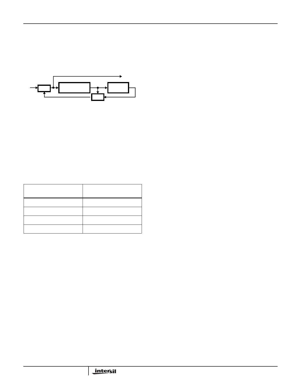
Scrambling is done by a division using a prescribed
polynomial as shown in Figure 9. A shift register holds the
last quotient and the output is the exclusive-or of the data
and the sum of taps in the shift register. The taps are
programmable. The transmit scrambler seed for the long
preamble or for the short preamble can be set with CR36 or
CR37.
SERIAL DATA
IN
XOR
Z-1 Z-2 Z-3 Z-4
SERIAL
DATA OUT
Z-5 Z-6 Z-7
XOR
FIGURE 9. SCRAMBLING PROCESS
For the 1Mbps DBPSK data rates and for the header in all
rates, the data coder implements the desired DBPSK coding
by differential encoding the serial data from the scrambler
and driving both the I and Q output channels together. For
the 2Mbps DQPSK data rate, the data coder implements the
desired coding as shown in the DQPSK Data Encoder table.
This coding scheme results from differential coding of dibits
(2 bits). Vector rotation is counterclockwise although bits 6
and 7 of configuration register CR 1 can be used to reverse
the rotation sense of the TX or RX signal if desired.
TABLE 4. DQPSK DATA ENCODER
PHASE SHIFT
DIBIT PATTERN (d0, d1)
d0 IS FIRST IN TIME
0
00
+90
01
+180
11
-90
10
Spread Spectrum Modulator Description
The modulator is designed to generate DBPSK, DQPSK, and
CCK spread spectrum signals. The modulator is capable of
automatically switching its rate where the preamble is
DBPSK modulated, and the data and/or header are
modulated differently. The modulator can support date rates
of 1, 2, 5.5 and 11Mbps. The programming details to set up
the modulator are given at the introductory paragraph of this
section. The HFA3861B utilizes Quadraphase (I/Q)
modulation at baseband for all modulation modes.
In the 1Mbps DBPSK mode, the I and Q Channels are
connected together and driven with the output of the
scrambler and differential encoder. The I and Q Channels
are then both multiplied with the 11-bit Barker word at the
spread rate. The I and Q signals go to the Quadrature
upconverter (HFA3724) to be modulated onto a carrier.
Thus, the spreading and data modulation are BPSK
modulated onto the carrier.
For the 2Mbps DQPSK mode, the serial data is formed into
dibits or bit pairs in the differential encoder as detailed
above. One of the bits from the differential encoder goes to
the I Channel and the other to the Q Channel. The I and Q
Channels are then both multiplied with the 11-bit Barker
word at the spread rate. This forms QPSK modulation at the
symbol rate with BPSK modulation at the spread rate.
Transmit Filter Description
To minimize the requirements on the analog transmit
filtering, the transmit section shown in Figure 11 has an
output digital filter. This filter is a Finite Impulse Response
(FIR) style filter whose shape is set by tap coefficients. This
filter shapes the spectrum to meet the radio spectral mask
requirements while minimizing the peak to average
amplitude on the output. To meet the particular spread
spectrum processing gain regulatory requirements in Japan,
an extra FIR filter shape has been included that has a wider
main lobe. This increases the 90% power bandwidth from
about 11MHz to 14MHz. It has the unavoidable side effect of
increasing the amplitude modulation, so the available
transmit power is compromised by 2dB when using this filter
(CR 11 bit 5). The receive section Channel Matched Filter
(CMF) is also tailored to match the characteristics of the
transmit filter.
CCK Modulation
The spreading code length is 8 and based on
complementary codes. The chipping rate is 11Mchip/s and
the symbol duration is exactly 8 complex chips long. The
following formula is used to derive the CCK code words that
are used for spreading both 5.5 and 11Mbps:
c
=
e j ( ϕ1
+
ϕ2
+
ϕ3
+
ϕ4),
ej(ϕ1
+
ϕ3
+
ϕ4),
j
e
(ϕ1
+
ϕ2
+
ϕ4
)
,
–ej(ϕ1
+
ϕ4
)
,
j
e
(
ϕ1
+
ϕ2
+
ϕ3
)
,
e
j
(
ϕ1
+
ϕ3),
–e
j
(
ϕ1
+
ϕ2),
ejϕ1
(LSB to MSB), where c is the code word.
The terms: ϕ1, ϕ2, ϕ3, and ϕ4 are defined below for
5.5Mbps and 11Mbps.
This formula creates 8 complex chips (LSB to MSB) that are
transmitted LSB first. The coding is a form of the generalized
Hadamard transform encoding where ϕ1 is added to all code
chips, ϕ2 is added to all odd code chips, ϕ3 is added to all
odd pairs of code chips and ϕ4 is added to all odd quads of
code chips.
The phases ϕ1 modify the phase of all code chips of the
sequence and are DQPSK encoded for 5.5 and 11Mbps.
This will take the form of rotating the whole symbol by the
appropriate amount relative to the phase of the preceding
symbol. Note that the last chip of the symbol defined above
is the chip that indicates the symbol’s phase.
11
Share Link: 