W216 データシートの表示(PDF) - Cypress Semiconductor
部品番号
コンポーネント説明
一致するリスト
W216 Datasheet PDF : 14 Pages
| |||
PRELIMINARY
W216
Serial Data Interface
The W216 features a two-pin, serial data interface that can be
used to configure internal register settings that control partic-
ular device functions. Upon power-up, the W216 initializes with
default register settings, therefore the use of this serial data
interface is optional. The serial interface is write-only (to the
clock chip) and is the dedicated function of device pins SDATA
and SCLOCK. In motherboard applications, SDATA and
SCLOCK are typically driven by two logic outputs of the
chipset. Clock device register changes are normally made
upon system initialization, if any are required. The interface
can also be used during system operation for power manage-
ment functions. Table 3 summarizes the control functions of
the serial data interface.
Operation
Data is written to the W216 in eleven bytes of eight bits each.
Bytes are written in the order shown in Table 4.
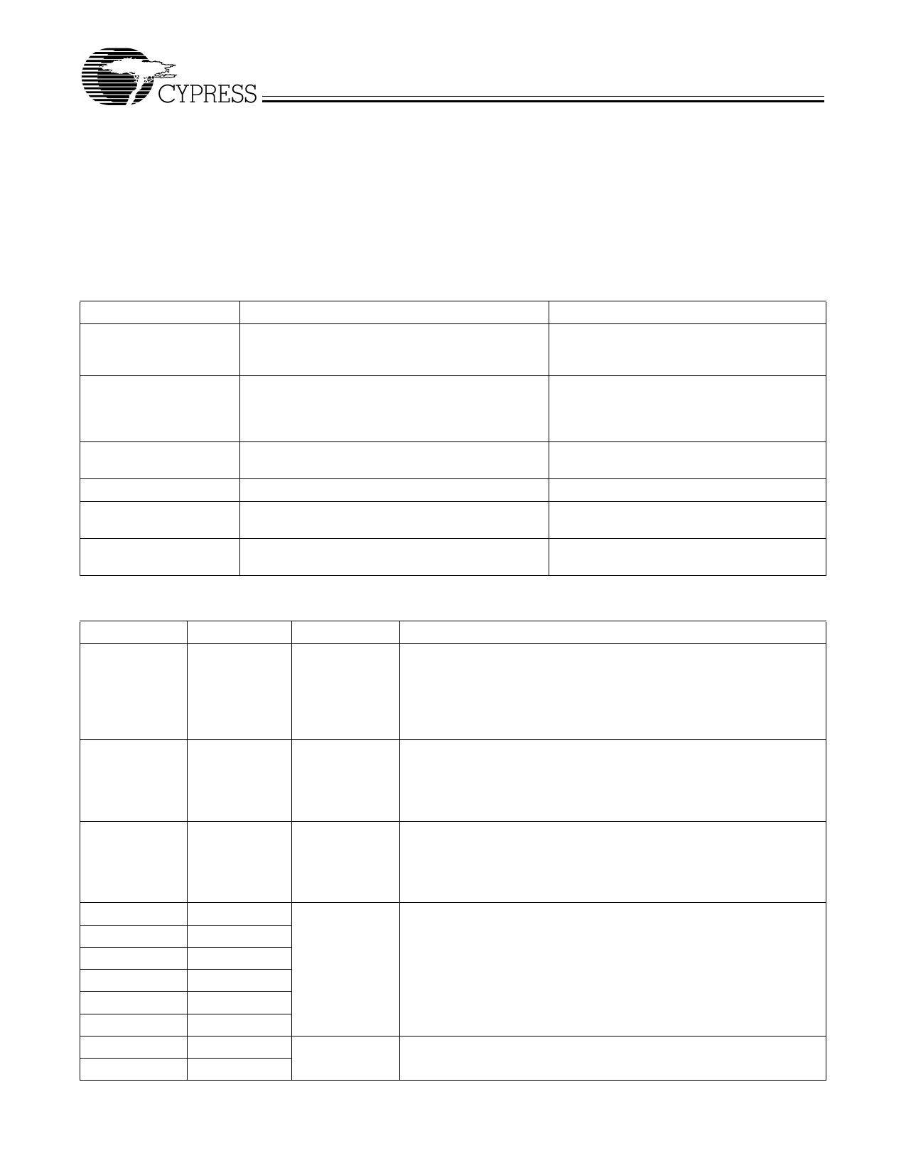
Table 3. Serial Data Interface Control Functions Summary
Control Function
Description
Common Application
Output Disable
Any individual clock output(s) can be disabled. Dis- Unused outputs are disabled to reduce EMI
abled outputs are actively held low.
and system power. Examples are clock out-
puts to unused PCI slots.
CPU Clock Frequency
Selection
Provides CPU/PCI frequency selections alternate
to the selections that are provided by the FS0:3
pins. Frequency is changed in a smooth and con-
trolled fashion.
For alternate microprocessors and power
management options. Smooth frequency tran-
sition allows CPU frequency change under
normal system operation.
Spread Spectrum
Enabling
Enables or disables spread spectrum clocking.
For EMI reduction.
Output Three-state
Puts all clock outputs into a high-impedance state. Production PCB testing.
Test Mode
All clock outputs toggle in relation to X1 input, inter- Production PCB testing.
nal PLL is bypassed. Refer to Table 5.
(Reserved)
Reserved function for future device revision or pro- No user application. Register bit must be writ-
duction device testing.
ten as 0.
Table 4. Byte Writing Sequence
Byte Sequence Byte Name
1
Slave Address
2
Command
Code
3
Byte Count
4
Data Byte 0
5
Data Byte 1
6
Data Byte 2
7
Data Byte 3
8
Data Byte 4
9
Data Byte 5
10
Data Byte 6
11
Data Byte 7
Bit Sequence
11010010
Don’t Care
Don’t Care
Refer to Table 5
Don’t Care
Byte Description
Commands the W216 to accept the bits in Data Bytes 0–7 for internal
register configuration. Since other devices may exist on the same com-
mon serial data bus, it is necessary to have a specific slave address for
each potential receiver. The slave receiver address for the W216 is
11010010. Register setting will not be made if the Slave Address is not
correct (or is for an alternate slave receiver).
Unused by the W216, therefore bit values are ignored (“don’t care”). This
byte must be included in the data write sequence to maintain proper byte
allocation. The Command Code Byte is part of the standard serial com-
munication protocol and may be used when writing to another ad-
dressed slave receiver on the serial data bus.
Unused by the W216, therefore bit values are ignored (“don’t care”). This
byte must be included in the data write sequence to maintain proper byte
allocation. The Byte Count Byte is part of the standard serial communi-
cation protocol and may be used when writing to another addressed
slave receiver on the serial data bus.
The data bits in Data Bytes 0–7 set internal W216 registers that control
device operation. The data bits are only accepted when the Address
Byte bit sequence is 11010010, as noted above. For description of bit
control functions, refer to Table 5, Data Byte Serial Configuration Map.
Unused by the W216, therefore bit values are ignored (“don’t care”).
5
Share Link: 