VT82885 データシートの表示(PDF) - Unspecified
部品番号
コンポーネント説明
一致するリスト
VT82885 Datasheet PDF : 16 Pages
| |||
VIA Technologies, Inc.
VT82885
Real Time Clock
by the RESET# pin. SQWE is a read/write
bit.
DM
The Data Mode (DM) bit indicates whether
time and calendar information is in binary or
BCD format. The DM bit is set by the
program to the appropriate format and can
be read as required. This bit is not modified
by internal functions or RESET#. A one in
DM signifies binary data while a zero in DM
specifies Bnary Coded Decimal (BCD) data.
24/12
The 24/12 control bit establishes the format
of the hours byte. A one indicates the 24-
hour mode and a zero indicates the 12-hour
mode. This bit is read/write and is not
affected by internal functions of RESET#.
DSE
The Daylight Savings Enable (DSE) bit is a
read/write bit which enables two special
updates when DSE is set to one. On the first
Sunday in April the time increments from
1:59:59 AM to 3:00:00 AM. On the last
Sunday in October when the time reaches
1:59:59 AM it changes to 1:00:00 AM. These
special updates do not occur when the DSE
bit is a zero. This bit is not affected by
internal functions or RESET#.
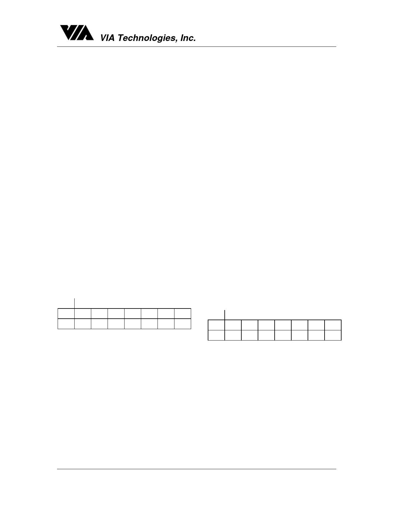
REGISTER C
MSB
LSB
BIT 7 BIT 6 BIT 5 BIT 4 BIT 3 BIT 2 BIT 1 BIT 0
IRQF PF AF UF 0
0
0
0
IRQF
The interrupt Request Flag (IRQF) bit is set
to a one when one or more of the following
are true:
PF = PIE = 1
AF = AIE = 1
UF = UIE = 1
That is, IRQF = PF • PIE + AF • AIE + UF •
UIE.
Any time the IRQF bit is one, the IRQ# pin is
driven low. All flag bits are cleared after
Register C is read by the program or when
the RESET# pin is low.
ABSOLUTE MAXIMUM RATINGS*
PF
The Periodic Interrupt Flag (PF) is a read-
only bit whcih is set to a one when an edge
is detected on the selected tap of the divider
chain. The RS3 through RS0 bits establish
the periodic rate. PF is set to a one
independent of the state of the PIE bit.
When both PF and PIE are ones, the IRQ#
signal is active and will set the IRQF bit. The
PF bit is cleared by a RESET# or a software
read of Register C.
AF
A one in the Alarm Interrupt Flag (AF) bit
indicates that the current time has matched
the alarm time. If the AIE bit is also a one,
the IRQ# pin will go low and a one will
appear in the IRQF pin. UF is cleared by
reading Register C or a RESET#.
UF
The Update Ended Interrupt Flag (UF) bit is
set after each update cycle. When the UIE
bit is set to one, the one in UF causes the
IRQF bit to be a one which will assert the
IRQ# pin. UF is cleared by reading Register
C or a RESET#.
BIT 0 THROUGH BIT 3
These are unused bits of the status Register
C. These bits always read zero and cannot
be written.
REGISTER D
MSB
LSB
BIT 7 BIT 6 BIT 5 BIT 4 BIT 3 BIT 2 BIT 1 BIT 0
VRT 0
0
0
0
0
0
0
VRT
This bit is not writeable and should always
be one when read. If a zero is ever present,
an exhausted external lithium energy source
is indicated and both the contents of the
RTC data and RAM data are questionable.
This bit is unaffected by RESET#.
BIT 6 THROUGH BIT 0
The remaining bits of Register D are not
usable. They cannot be written and, when
read, they will always read zero.
10
Share Link: 