SC4608EVB データシートの表示(PDF) - Semtech Corporation
部品番号
コンポーネント説明
一致するリスト
SC4608EVB Datasheet PDF : 19 Pages
| |||
SC4608
POWER MANAGEMENT
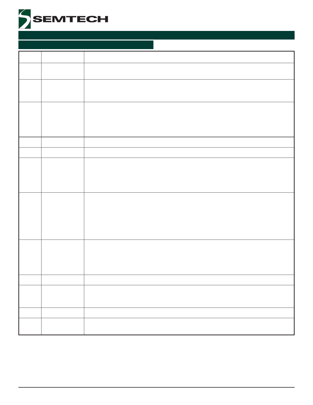
Pin Descriptions (Cont.)
Pin #
Pin Name Pin Function
6
PGOOD
Power good open drain output. Low when the output is below the power good threshold
level.
7
SS
Soft start. A capacitor to ground sets the soft start time. The soft start time is independent
of switching frequency and is defined as SS = 0 .09 • C. Where C is the external
capacitor in nF and SS is the soft start time in ms.
8
VSENSE
This pin is the inverting input of the voltage amplifier and serves as the output voltage
feedback point for the Buck converter. VSENSE is compared to an internal reference value
of 0.5V. VSENSE is hardwired to the output voltage when an output of 0.5V is desired.
For higher output voltages, a resistor divider network is necessary (R7 and R9 in the Typical
Application Circuit Diagram).
9
AGND
Analog ground.
10
PGND
Power ground.
11
DRVL
DRVL drives the gate of the low side (synchronous rectifier) MOSFET. The output drivers
are rated for 1A peak currents. The PWM circuitry provides complementary drive signals to
the output stages. The cross conduction of the external MOSFETs is prevented by
monitoring the voltage on the driver pins of the MOSFET pair in conjunction with a time
delay optimized for FET turn-off characteristics.
12
PHASE
The PHASE pin is used to limit current in the high side MOSFET. The SC4608 uses the
voltage across the VIN and ISET pin in order to set the current limit. The current limit
threshold is set by the value of an external resistor (R3 in the Typical Application Circuit
Diagram). Current limiting is performed by comparing the voltage drop across the sense
resistor with the voltage drop across the drain to source resistance of the high side
MOSFET during the MOSFET’s conduction period. The voltage drop across the drain to
source resistance of the high side MOSFET is obtained from the VIN and PHASE pin.
13
DRVH
DRVH drives the gate of the high side (main switch) MOSFET. The output drivers are rated
for 1A peak currents. The PWM circuitry provides complementary drive signals to the
output stages. The cross conduction of the external MOSFETs is prevented by monitoring
the voltage on the driver pins of the MOSFET pair in conjunction with a time delay
optimized for FET turn-off characteristics.
14
NC
No connection.
15
BST
This pin enables the converter to drive an N-Channel high side MOSFET. BST connects to
the external charge pump circuit. The charge pump circuit boosts the BST pin voltage to a
sufficient gate-to-source voltage level for driving the gate of the high side MOSFET.
16
PVDD
Power supply voltage for low side MOSFET.
Thermal Pad Pad for heatsinking purposes. Connect to ground plane using multiple vias. Not connected
internally.
2006 Semtech Corp.
6
www.semtech.com
Share Link: 