NJU3503L データシートの表示(PDF) - Japan Radio Corporation
部品番号
コンポーネント説明
一致するリスト
NJU3503L Datasheet PDF : 60 Pages
| |||
NJU3503
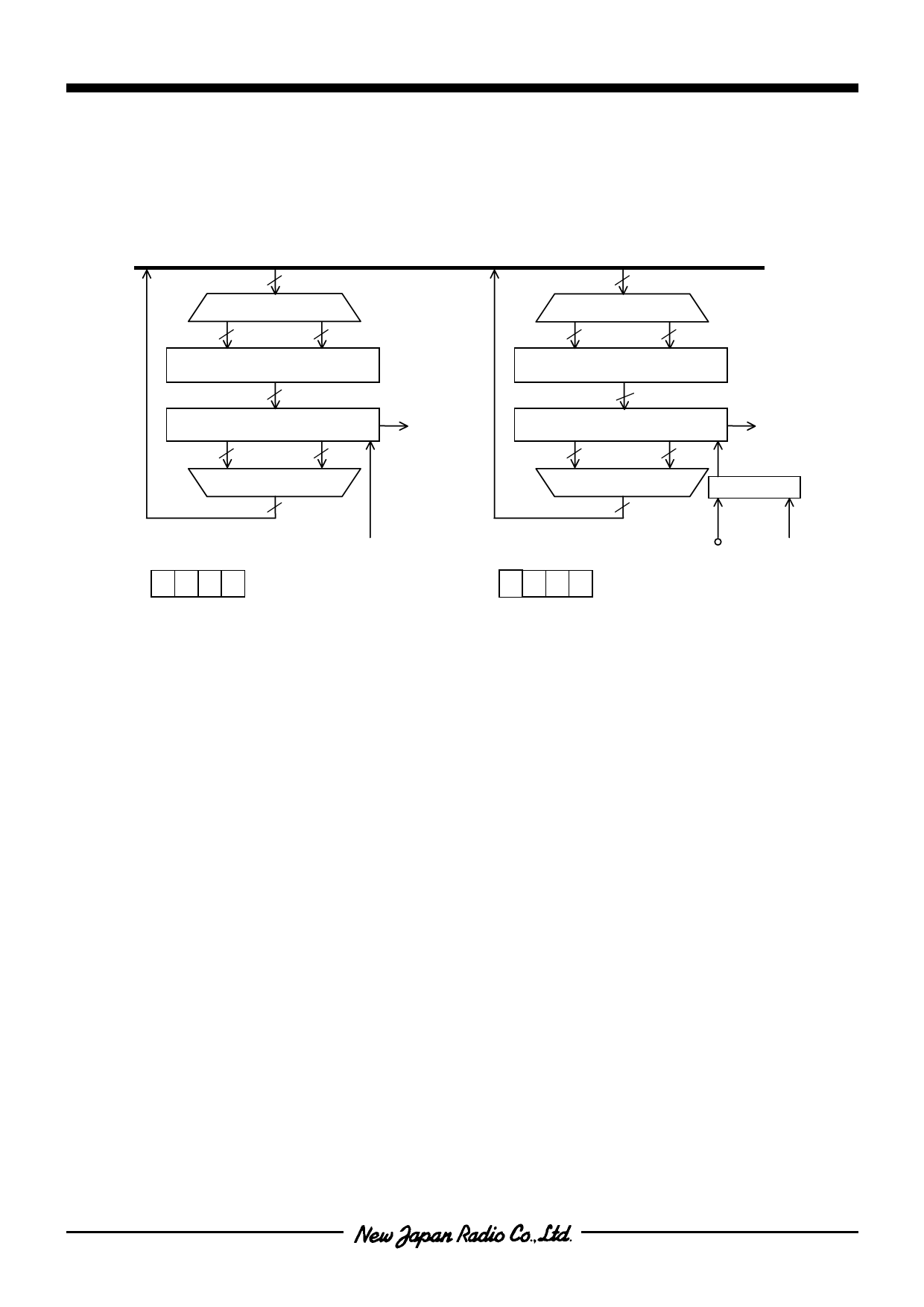
s TIMER
The NJU3503 prepares a couple of Programmable Timer / Counter(Timer1,Timer2) consisted of the 8-bit
binary counter.
[ Structure of Timer / Counter ]
DB (4-bit)
4
DEMULTIPLEXER
4
4
INITIAL VALUE REGISTER1
4
DEMULTIPLEXER
4
4
INITIAL VALUE REGISTER2
8
8-bit TIMER / COUNTER 1
4
4
MULTIPLEXER
4
TIMER1
Interrupt
8
8-bit TIMER / EVENT COUNTER 2
4
4
TIMER2
Interrupt
MULTIPLEXER
4
SELECTOR
INTERNAL CLOCK
CNTI
PHY3 − b2 b1 b0
PHY5 b3 b2 b1 b0
TIMER1 CONTROL REGISTER
TIMER2 CONTROL REGISTER
INTERNAL
CLOCK
Timer1 counts only the internal clock and Timer2 counts either of the internal clock or the external clock in
accordance with the condition of bit2(b2) of the Timer2 Control Register(PHY5). The initial value of the
counter can be set the optional value by the program which instructs to write the data(a value of the time-
interval or the event-count) into the Initial Value Register(Timer1 or Timer2 is set the each value independently).
In enabling the timer interrupt, when the counter counts from “FF” to “00” (overflow), the timer interrupt request
occurs and the internal interrupt process starts the own operation.
In the repeat mode of the Timer operation, when the counter overflows, the initial value is loaded into the
counter automatically and the counter continues the count from the loaded initial value(Auto re-load function:
See the repeat mode of the Timer operation timing chart). In the single mode of the Timer operation, when the
counter overflows, the count is stopped(See the single mode of the Timer operation timing chart). For starting
the count operation again, the start bit(LSB) of the Timer1 or Timer2 Control Register must be set to “1”. The
latest initial value is set into the counter and the counter starts the count.
In enabling the interrupt operation, when the counter overflows, the Timer / Counter overflow flag is set to "1"
and the internal interrupt process starts to the own operation. In disabling the timer interrupt, the Timer /
Counter overflow flag is not set. The Timer / Counter overflow flag is initialized by the Timer Start or the Reset
signal.
The internal clock into the counter is the divided clock from the internal prescaler. The frequency of the
clock can be selected by the mask option from the following which are the dividing numbers based on the
inverse of the 1-instruction executing period(1/fOSC x 6).
1/2, 1/4, 1/8, 1/16, 1/32,1/64, 1/128, 1/256, 1/512, 1/1024, 1/2048,1/4096
When the bit2(b2) of the Timer1 / Prescaler Control Register is set to "1", the prescaler generating the
internal count clock is stopped the operation. As the result, Timer / Counter stops the count operation.
In the external clock operation of Timer2, the external clock must be input to CNTI terminal. The Timer2
Control Register selects either the internal clock operation or the external clock operation.
- 21 -
Share Link: 