NJU3503L データシートの表示(PDF) - Japan Radio Corporation
部品番号
コンポーネント説明
一致するリスト
NJU3503L Datasheet PDF : 60 Pages
| |||
NJU3503
• STACK POINTER(SP)
STACK POINTER(SP) consists of the 3 bits binary counter. SP indicates the number of next operating
position in the STACK. It counts one up(increment) after the subroutine call(CALL) or the interrupt
operation, and it counts one down(decrement) after the return(RET or RETI) operation.
Data storing operation to STACK after that SP overflowed (over than 7) or under flowed(under than 0),
breaks the former held data in STACK. Therefore the subroutine nesting level must be cautioned in the
application program.
SP condition is set to "0" on “RESET” operation.
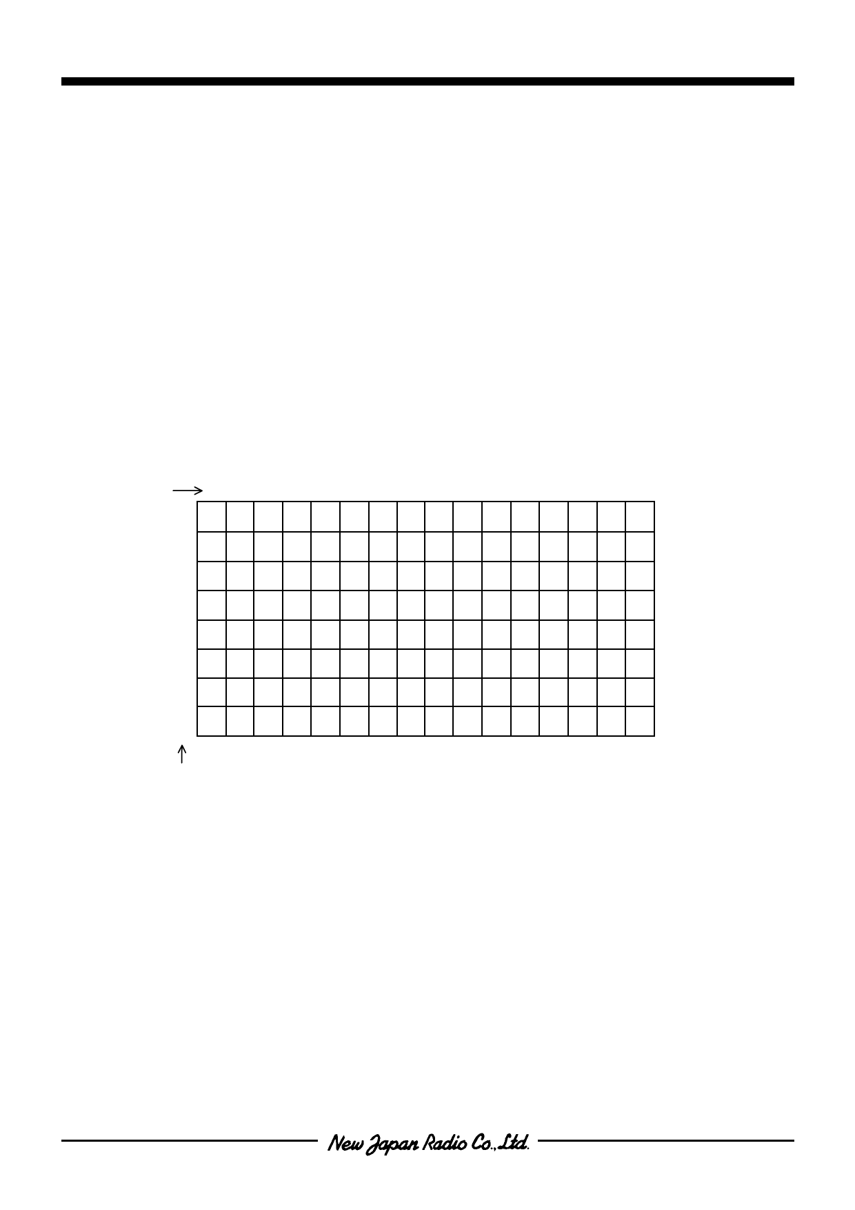
• DATA MEMORY(RAM)
DATA MEMORY(RAM) is formed with the 4-bit length a word. The NJU3503 prepares 128 words(512
bits) RAM. The data formed with the 4-bit length a word can be read/written from/to RAM, and the data
formed with the 1-bit length in a word can be set, reset, or tested by the bit-operation instruction.
The RAM address is indicated indirectly by X-reg and Y-reg. The lower 3 bits(b0,b1,b2) in X-reg are used
as the RAM address pointer and higher a bit (b3) is not used.
[ RAM ADDRESS MAP ]
Y-reg
0 1 2 3 4 5 6 7 8 9 A B C D E F [HEX]
0
1
2
3
4
5
6
7
[HEX]
X-reg
- 10 -
Share Link: 