MIC2590B データシートの表示(PDF) - Micrel
部品番号
コンポーネント説明
一致するリスト
MIC2590B Datasheet PDF : 23 Pages
| |||
Micrel, Inc.
MIC2590B
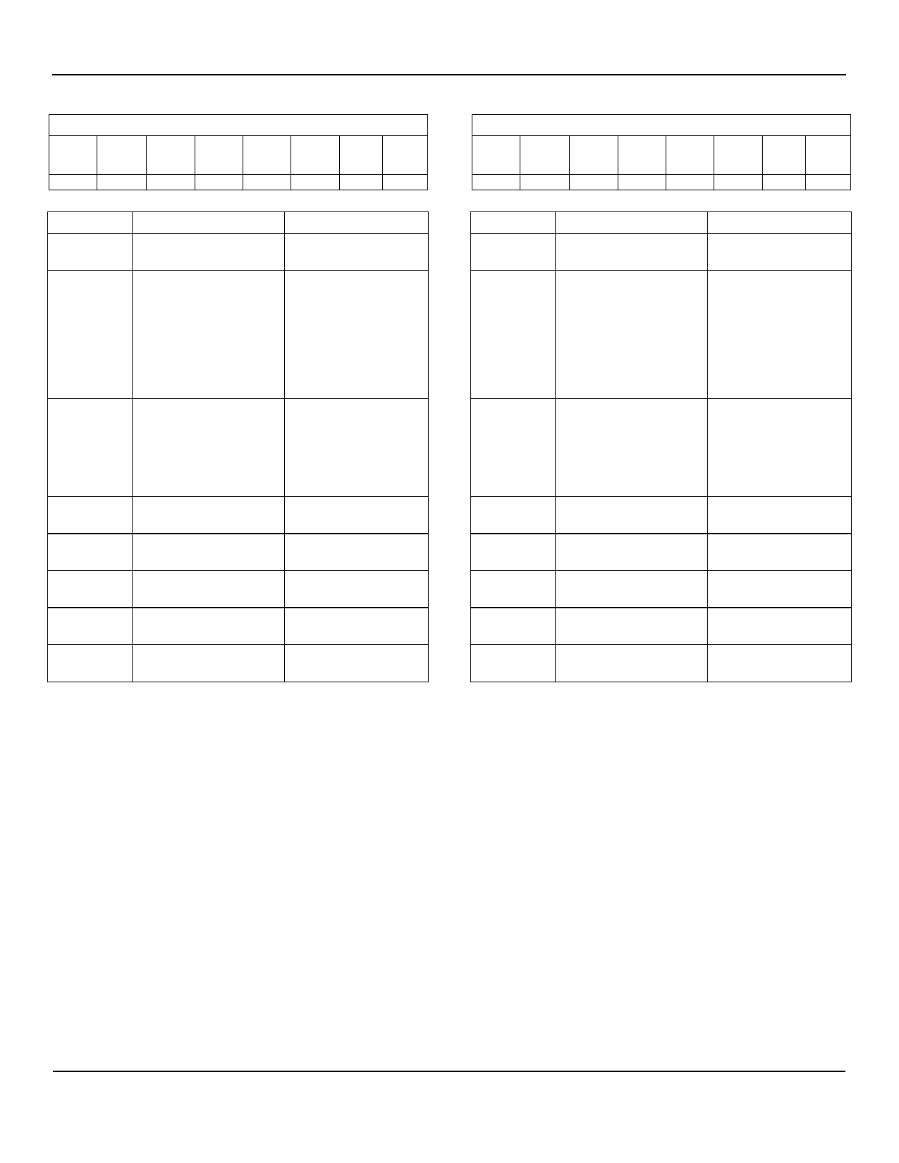
Status Register, Slot A (STATA), 8-Bits Read Only
D[7]
read-only
FAULTA
D[6]
read-only
MAINA
D[5]
read-only
VAUXA
D[4]
read-
write
VAUXAF
D[3]
read-
write
12MVAF
D[2]
read-
write
12VAF
D[1]
read-
write
5VAF
D[0]
read-
write
3VAF
Bit(s)
FALUTA
MAINA
VAUXA
VAUXFA
12MVFA
12VFA
5VFA
3VFA
Function
FAULT Pin Status, Slot
A
MAIN Enable Status,
Slot A
VAUX Enable Status,
Slot A
Overcurrent Fault
VAUX Supply
Overcurrent Fault
-12V Supply
Overcurrent Fault
12V Supply
Overcurrent Fault
5V Supply
Overcurrent Fault
3V Supply
Operation
Notes 1 & 2
Represents actual
state (on/off) of the
four main power
outputs for Slot A.
(+12V, +5V, +3.3V
and -12V)
1 = MAIN Power On
0 = MAIN Power Off
Represents actual
state (on/off) of the
auxiliary power
outputs for Slot A.
1 = MAIN Power On
0 = MAIN Power Off
1 = Fault
0 = No Fault
1 = Fault
0 = No Fault
1 = Fault
0 = No Fault
1 = Fault
0 = No Fault
1 = Fault
0 = No Fault
Power-Up Default Value:
0000 0000b = 00h
Read Command Byte (R/W): 0000 0100b = 04h
The power-up default value is 00h. The slot is disabled
upon power-up, i.e., all supply outputs are off. In response
to an overcurrent fault condition, writing a logical 1 back
into the active (or set) bit position will clear the bit and de-
assert /INT. The status of the /FAULTA pin is not affected
by reading the Status Register.
Status Register, Slot B (STATB), 8-Bits Read Only
D[7]
read-only
FAULTB
D[6]
read-only
MAINB
D[5]
read-only
VAUXB
D[4]
read-
write
VAUXBF
D[3]
read-
write
12MVBF
D[2]
read-
write
12VBF
D[1]
read-
write
5VBF
D[0]
read-
write
3VBF
Bit(s)
FALUTB
MAINB
VAUXB
VAUXFB
12MVFB
12VFB
5VFB
3VFB
Function
FAULT Pin Status, Slot
B
MAIN Enable Status,
Slot B
VAUX Enable Status,
Slot B
Overcurrent Fault
VAUX Supply
Overcurrent Fault
-12V Supply
Overcurrent Fault
12V Supply
Overcurrent Fault
5V Supply
Overcurrent Fault
3V Supply
Operation
Notes 1 & 2
Represents actual
state (on/off) of the
four main power
outputs for Slot B.
(+12V, +5V, +3.3V
and -12V)
1 = MAIN Power On
0 = MAIN Power Off
Represents actual
state (on/off) of the
auxiliary power
outputs for Slot B.
1 = MAIN Power On
0 = MAIN Power Off
1 = Fault
0 = No Fault
1 = Fault
0 = No Fault
1 = Fault
0 = No Fault
1 = Fault
0 = No Fault
1 = Fault
0 = No Fault
Power-Up Default Value:
0000 0000b = 00h
Read Command Byte (R/W): 0000 0101b = 05h
The power-up default value is 00h. The slot is disabled
upon power-up, i.e., all supply outputs are off. In response
to an overcurrent fault condition, writing a logical 1 back
into the active (or set) bit position will clear the bit and de-
assert /INT. The status of the /FAULTB pin is not affected
by reading the Status Register.
Note 1.
Note 2.
1 = /FAULT[A/B] pin asserted, indicating a fault condition (/FAULT is LOW).
0 = /FAULT[A/B] pin is de-asserted (/FAULT is HIGH).
If FAULT[A/B] has been set by an overcurrent condition on one (or more) of the main outputs, the corresponding ON[A/B] must go LOW
to reset FAULT. If FAULT[A/B] has been set by an overcurrent on a VAUX output, the corresponding AUXEN[A/B] must go LOW to reset
FAULT. If an overcurrent has occurred on both a main output and VAUX output of a slot, both ON[A/B] and AUXEN[A/B] of the
corresponding slot must go LOW to reset FAULT.
The FAULT bits, and the /FAULT pins, are not active when the MIC2590B power paths are controlled by the System Management
Interface (SMBus). When using SMI power path control for a slot, the AUXEN and ON pins for that slot must be tied to ground.
September 2008
16
M9999-091808
Share Link: 