EL7562 データシートの表示(PDF) - Elantec -> Intersil
部品番号
コンポーネント説明
一致するリスト
EL7562 Datasheet PDF : 10 Pages
| |||
EL7562C - Preliminary
Monolithic 2 Amp DC:DC Step-down Regulator
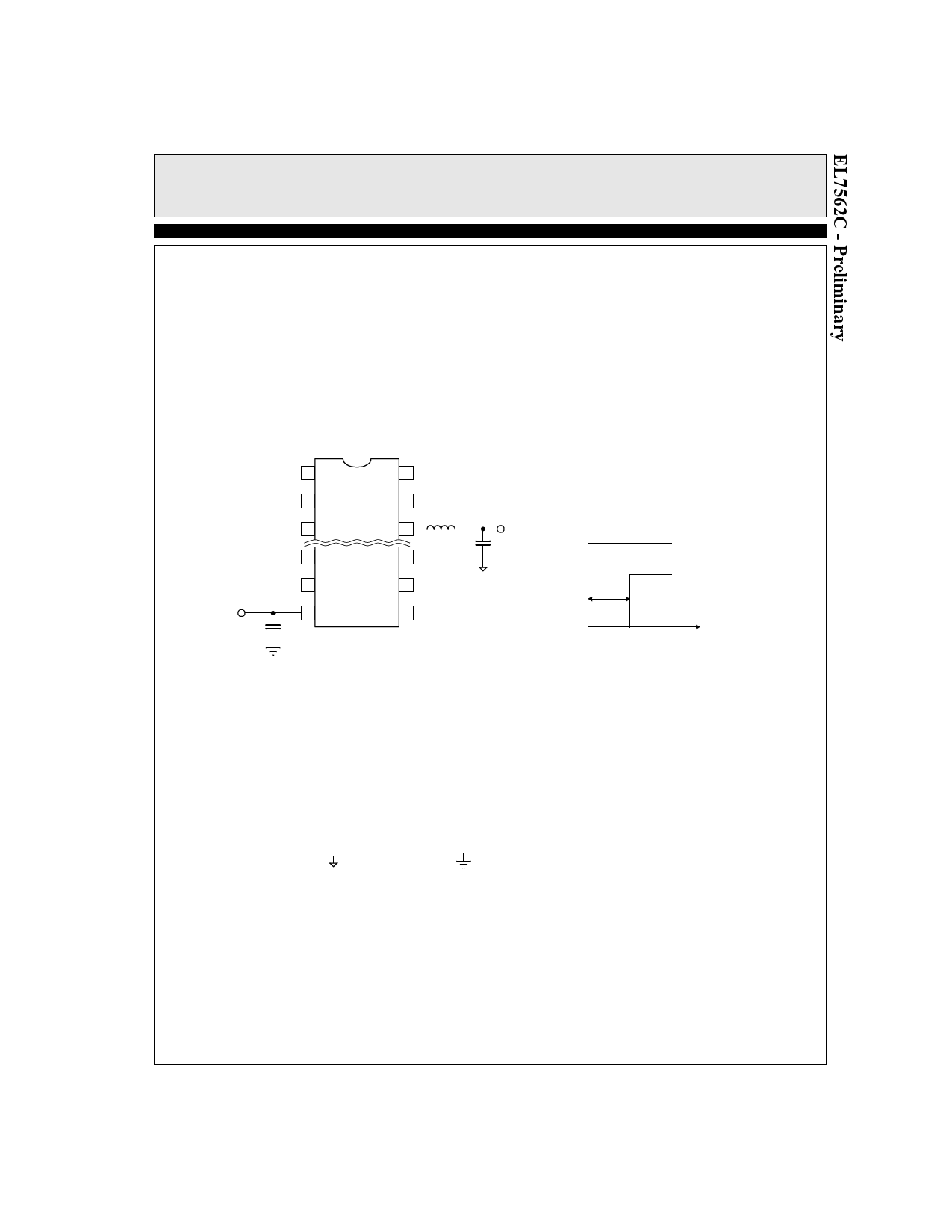
Start-up Delay
A capacitor can be added to the EN pin to delay the con-
verter start-up (Figure 2) by utilizing the pull-up current.
The delay time is approximately:
td(ms) = 1200 × C(µF)
1
16
2
15
3
14
6
11
7
10
8
9
C
EL7562C
VOUT
VIN
VO
td
TIME
Figure 2. Start-up Delay
Layout Considerations
The layout is very important for the converter to func-
tion properly. Power Ground ( ) and Signal Ground (---)
should be separated to ensure that the high pulse current
in the Power Ground never interferes with the sensitive
signals connected to Signal Ground. They should only
be connected at one point (normally at the negative side
of either the input or output capacitor.)
The trace connected to pin 14 (FB) is the most sensitive
trace. It needs to be as short as possible and in a “quiet”
place, preferably between PGND or SGND traces.
In addition, the bypass capacitor connected to the VDD
pin needs to be as close to the pin as possible.
The heat of the chip is mainly dissipated through the
PGND pins. Maximizing the copper area around these
pins is preferable. In addition, a solid ground plane is
always helpful for the EMI performance.
The demo board is a good example of layout based on
these principles. Please refer to the EL7562C Applica-
tion Brief for the layout.
9
Share Link: 