ADIS16251(RevPrA) データシートの表示(PDF) - Analog Devices
部品番号
コンポーネント説明
一致するリスト
ADIS16251 Datasheet PDF : 20 Pages
| |||
Preliminary Technical Data
DATA OUTPUT REGISTER ACCESS
The ADIS16251 provides access to calibrated rotation
measurements, relative angle estimates, power supply
measurements, temperature measurements, and an auxiliary
12-bit ADC channel. This output data is continuously updating
internally, regardless of user read rates. The following bit map
describes the structure of all output data registers in the
ADIS16251.
Table 5. Register Bit Map
MSB
LSB
ND EA D13 D12 D11 D10 D9 D8
D7 D6 D5 D4 D3 D2 D1 D0
Table 6 and provides all of the necessary details for accessing
each register’s data. Table 7 displays the output coding for the
ADIS16251
The MSB holds the new data (ND) indicator. When the output
registers are updated with new data, the ND bit goes to a 1 state.
After the output data is read, it returns to a 0 state. The EA bit is
used to indicate a system error or an alarm condition that can
result from a number of conditions, such as a power supply that
is out of the specified operating range. See the Status and
Diagnostics section for more details. The output data is either
12 bits or 14 bits in length. For all of the 12-bit output data, the
D13 bit and the D12 bit are assigned “don’t care” status.
The output data register map is located in
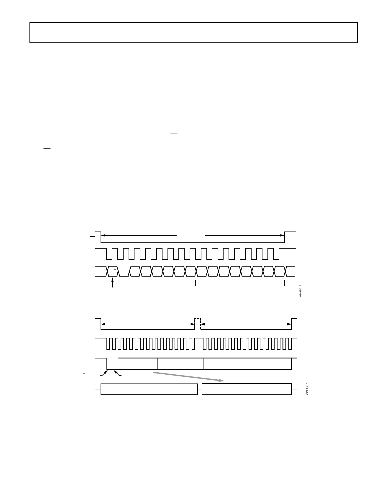
GYRO_OUT register. Figure 16 provides an example SPI read
cycle for this register.
Table 6. Data Output Register Information
Name
ENDURANCE
SUPPLY_OUT
GYRO_OUT
AUX_ADC
TEMP_OUT
ANGL_OUT
Function
Flash Memory Write Counter
Power Supply Data
Gyroscope Data
Auxiliary Analog Input Data
Sensor Temperature Data
Angle Output
Address
0x01, 0x00
0×03, 0×02
0×05, 0×04
0×0B, 0×0A
0×0D, 0×0C
0×0F, 0×0E
Resolution (Bits)
16
12
14
12
12
14
Data Format
Binary
Binary
Twos Complement
Binary
Twos Complement
Binary
Scale Factor
(per LSB)
N/A
1.832 mV
0.07326°/sec1
0.61 mV
+0.1453°C
0.03663°
Table 7. Output Coding Example, GYRO_OUT2, 3
Rate of Rotation
±80°/sec Range
±40°/sec Range
600°/sec
300°/sec
80°/sec
160°/sec
80°/sec
40°/sec
40°/sec
20°/sec
0.07326°/sec
0.03663°/sec
0°/sec
0°/sec
−0.07326°/sec
−0.03663°/sec
−40°/sec
−20°/sec
−80°/sec
−40°/sec
−320°/sec
−160°/sec
−600°/sec
−300°/sec
±20°/sec Range
150°/sec
80°/sec
20°/sec
10°/sec
0.018315°/sec
0°/sec
−0.018315°/sec
−10°/sec
−20°/sec
−80°/sec
−150°/sec
Binary Output
01 1111 1111 1111
01 0001 0001 0001
00 0100 0100 0100
00 0010 0010 0010
00 0000 0000 0001
00 0000 0000 0000
11 1111 1111 1111
11 1101 1101 1110
11 1011 1011 1100
10 1110 1111 0000
10 0000 0000 0000
HEX Output
0x1FFF
0x1110
0x0444
0x0222
0x0001
0x0000
0x3FFF
0x3DDE
0x3BBC
0x2EF0
0x2000
Decimal
8191
4368
1092
546
1
0
−1
−546
−1092
−4368
−8192
1 Assumes that the scaling is set to 80°/sec.
2 Two MSBs have been masked off and are not considered in the coding.
3 Nominal sensitivity and zero offset null performance are assumed.
Rev. PrA | Page 11 of 20
Share Link: 