5B34 データシートの表示(PDF) - Analog Devices
部品番号
コンポーネント説明
一致するリスト
5B34 Datasheet PDF : 8 Pages
| |||
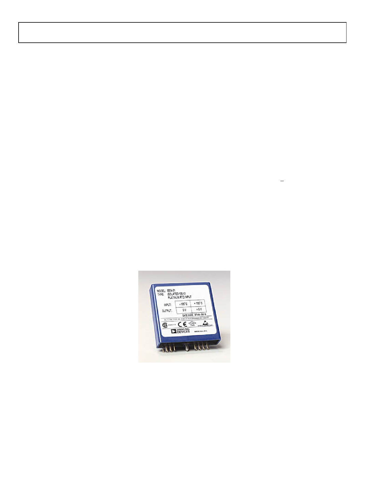
GENERAL DESCRIPTION
The 5B34 is a single-channel signal conditioning module that
amplifies, protects, filters, linearizes, and isolates a wide variety
of two and three-wire RTDs. For true four-wire RTD
measurements please refer to the 5B35 model.
The 5B34 protects the computer side from damage due to field-
side over-volatge faults. The module withstands 240 V rms at
the input terminals without damage thereby shielding the
internal computer-side circuitry from field-side over-voltage
conditions. In addition, the 5B34 is mix-and-match and hot
swappable with all other 5B Series input modules, so can be
inserted or removed from any socket in the same backplane
without disrupting system power.
Two identical sources provide excitation current for the RTD.
For three-wire RTDs, the second current flows through the
third RDT lead so as to cancel the effects of (equal) lead
resistance; this current also flows through a stable resistor laser-
trimmed to the RTD value that sets the differential amplifier
input and (module) output to zero volts at that scale point. The
current sources and the amplifier input are protected to
withstand input over-voltage up to 240 V rms.
A differential chopper-stabilized input amplifier provides stable
gain and exceptionally low drift. This allows the use of very low
RTD excitation current to minimize self-heating and preserve
.
5B34
measurement accuracy. Along with module gain and zero
settings, a feedback linearizer is laser-trimmed. Custom versions
of 5N34 can be laser-trimmed to meet special requirements.
Internal multi-pole low-pass filtering with a four-Hz cutoff (-
3dB) enhances normal-mode (noise on signal) and common-
mode (noise on signal return) rejection at 50/60 Hz, enabling
accurate measurement of small signals in high electrical noise.
Signal isolation by transformer coupling uses a proprietary
modulation technique for linear, stable and reliable
performance. The differential input circuit on the field side is
fully floating, eliminating the need for any input grounding. A
demodulator on the computer side of the signal transformer
recovers the original signal, which is then filtered and buffered
to provide a low-noise, low-impedance output signal. The
output common must be kept within +3V of power common.
A series output switch eliminates the need for external
multiplexing in many applications. The switch is turned on by
an active-low enable input. If the switch is to be on at all times,
the enable-input should be grounded to power common as it is
on the 5B01 and 5B08 backplanes.
.
Figure 2
Rev. 0 | Page 2 of 8
Share Link: 