MP1423DP データシートの表示(PDF) - Monolithic Power Systems
部品番号
コンポーネント説明
一致するリスト
MP1423DP Datasheet PDF : 11 Pages
| |||
TM
MP1423 – 3A, 23V, 385KHz STEP-DOWN CONVERTER
Output Rectifier Diode
The output rectifier diode supplies the current to
the inductor when the high-side switch is off. To
reduce losses due to the diode forward voltage
and recovery times, use a Schottky diode.
Choose a diode whose maximum reverse voltage
rating is greater than the maximum input voltage,
and whose current rating is greater than the
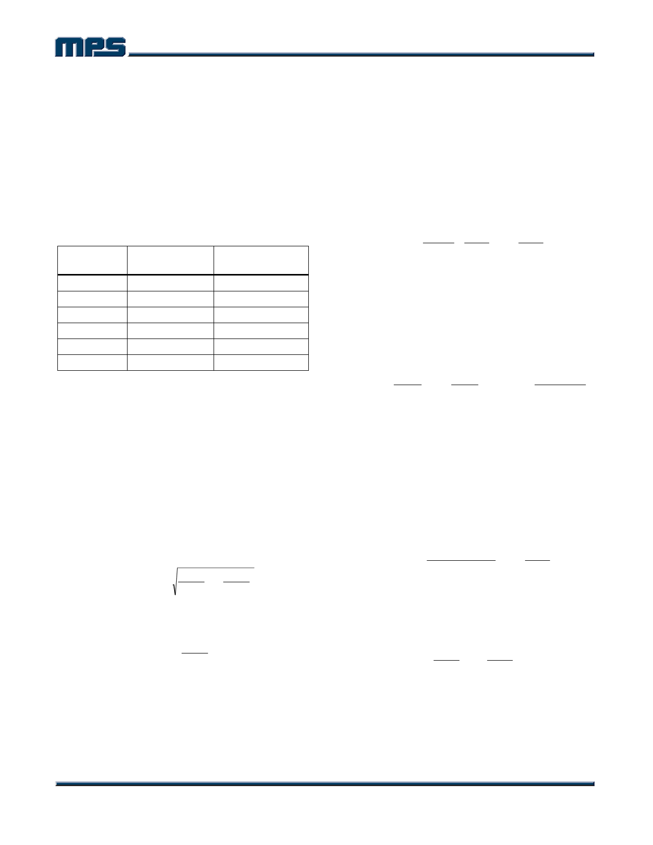
maximum load current. Table 2 lists example
Schottky diodes and manufacturers.
Table 2—Diode Selection Guide
Diode
SK33
SK34
B330
B340
MBRS330
MBRS340
Voltage/Current Manufacture
Rating
30V, 3A Diodes Inc.
40V, 3A Diodes Inc.
30V, 3A Diodes Inc.
40V, 3A Diodes Inc.
30V, 3A On Semiconductor
40V, 3A On Semiconductor
Input Capacitor
The input current to the step-down converter is
discontinuous, therefore a capacitor is required
to supply the AC current to the step-down
converter while maintaining the DC input
voltage. Use low ESR capacitors for the best
performance. Ceramic capacitors are preferred,
but tantalum or low-ESR electrolytic capacitors
may also suffice.
Since the input capacitor (C1) absorbs the input
switching current it requires an adequate ripple
current rating. The RMS current in the input
capacitor can be estimated by:
IC1 = ILOAD ×
VOUT
VIN
×⎜⎜⎛1−
⎝
VOUT
VIN
⎟⎞
⎟
⎠
The worst-case condition occurs at VIN = 2VOUT,
where:
IC1
=
ILOAD
2
For simplification, choose the input capacitor
whose RMS current rating greater than half of
the maximum load current.
The input capacitor can be electrolytic, tantalum
or ceramic. When using electrolytic or tantalum
capacitors, a small, high quality ceramic
capacitor, i.e. 0.1µF, should be placed as close to
the IC as possible.
When using ceramic capacitors, make sure that
they have enough capacitance to provide
sufficient charge to prevent excessive voltage
ripple at input. The input voltage ripple caused by
capacitance can be estimated by:
∆VIN
=
ILOAD ×
fS × C1
VOUT
VIN
× ⎜⎜⎝⎛1 −
VOUT
VIN
⎟⎟⎠⎞
Output Capacitor
The output capacitor is required to maintain the
DC output voltage. Ceramic, tantalum, or low
ESR electrolytic capacitors are recommended.
Low ESR capacitors are preferred to keep the
output voltage ripple low. The output voltage
ripple can be estimated by:
∆VOUT
=
VOUT
fS × L
× ⎜⎜⎝⎛1−
VOUT
VIN
⎟⎟⎠⎞ × ⎜⎜⎝⎛RESR
+
8
×
f
1
S×
C2
⎟⎟⎠⎞
Where L is the inductor value, C2 is the output
capacitance value, and RESR is the equivalent
series resistance (ESR) value of the output
capacitor.
In the case of ceramic capacitors, the impedance
at the switching frequency is dominated by the
capacitance. The output voltage ripple is mainly
caused by the capacitance. For simplification, the
output voltage ripple can be estimated by:
∆VOUT
=
8
×
VOUT
fS2 × L
×
C2
×
⎜⎜⎝⎛1 −
VOUT
VIN
⎟⎟⎠⎞
In the case of tantalum or electrolytic capacitors,
the ESR dominates the impedance at the
switching frequency. For simplification, the output
ripple can be approximated to:
∆VOUT
=
VOUT
fS × L
×
⎜⎜⎝⎛1 −
VOUT
VIN
⎟⎟⎠⎞ × RESR
The characteristics of the output capacitor also
affect the stability of the regulation system. The
MP1423 can be optimized for a wide range of
capacitance and ESR values.
MP1423 Rev. 1.1
www.MonolithicPower.com
6
1/6/2006
MPS Proprietary Information. Unauthorized Photocopy and Duplication Prohibited.
© 2006 MPS. All Rights Reserved.
Share Link: 