MP1423DP データシートの表示(PDF) - Monolithic Power Systems
部品番号
コンポーネント説明
一致するリスト
MP1423DP Datasheet PDF : 11 Pages
| |||
TM
MP1423 – 3A, 23V, 385KHz STEP-DOWN CONVERTER
APPLICATION INFORMATION
COMPONENT SELECTION
Setting the Output Voltage
The output voltage is set using a resistive
voltage divider from the output voltage to FB
pin. The voltage divider divides the output
voltage down to the feedback voltage by the
ratio:
VFB
=
VOUT
R2
R1 + R2
Where VFB is the feedback voltage and VOUT is
the output voltage.
Thus the output voltage is:
VOUT
= 1.22 × R1+ R2
R2
A typical value for R2 can be as high as 100kΩ,
but a typical value is 10kΩ. Using that value, R1
is determined by:
R1 = 8.18 × (VOUT − 1.22)(kΩ)
For example, for a 3.3V output voltage, R2 is
10kΩ, and R1 is 17kΩ.
Inductor
The inductor is required to supply constant
current to the output load while being driven by
the switched input voltage. A larger value
inductor will result in less ripple current that will
result in lower output ripple voltage. However,
the larger value inductor will have a larger
physical size, higher series resistance, and/or
lower saturation current. A good rule for
determining the inductance to use is to allow
the peak-to-peak ripple current in the inductor
to be approximately 30% of the maximum
switch current limit. Also, make sure that the
peak inductor current is below the maximum
switch current limit. The inductance value can
be calculated by:
L
=
VOUT
fS × ∆IL
× ⎜⎜⎝⎛1−
VOUT
VIN
⎟⎟⎠⎞
Where VIN is the input voltage, fS is the 385KHz
switching frequency, and ∆IL is the peak-to-
peak inductor ripple current.
Choose an inductor that will not saturate under
the maximum inductor peak current.
The peak inductor current can be calculated by:
ILP
= ILOAD
+
VOUT
2 × fS × L
× ⎜⎜⎝⎛1−
VOUT
VIN
⎟⎟⎠⎞
Where ILOAD is the load current.
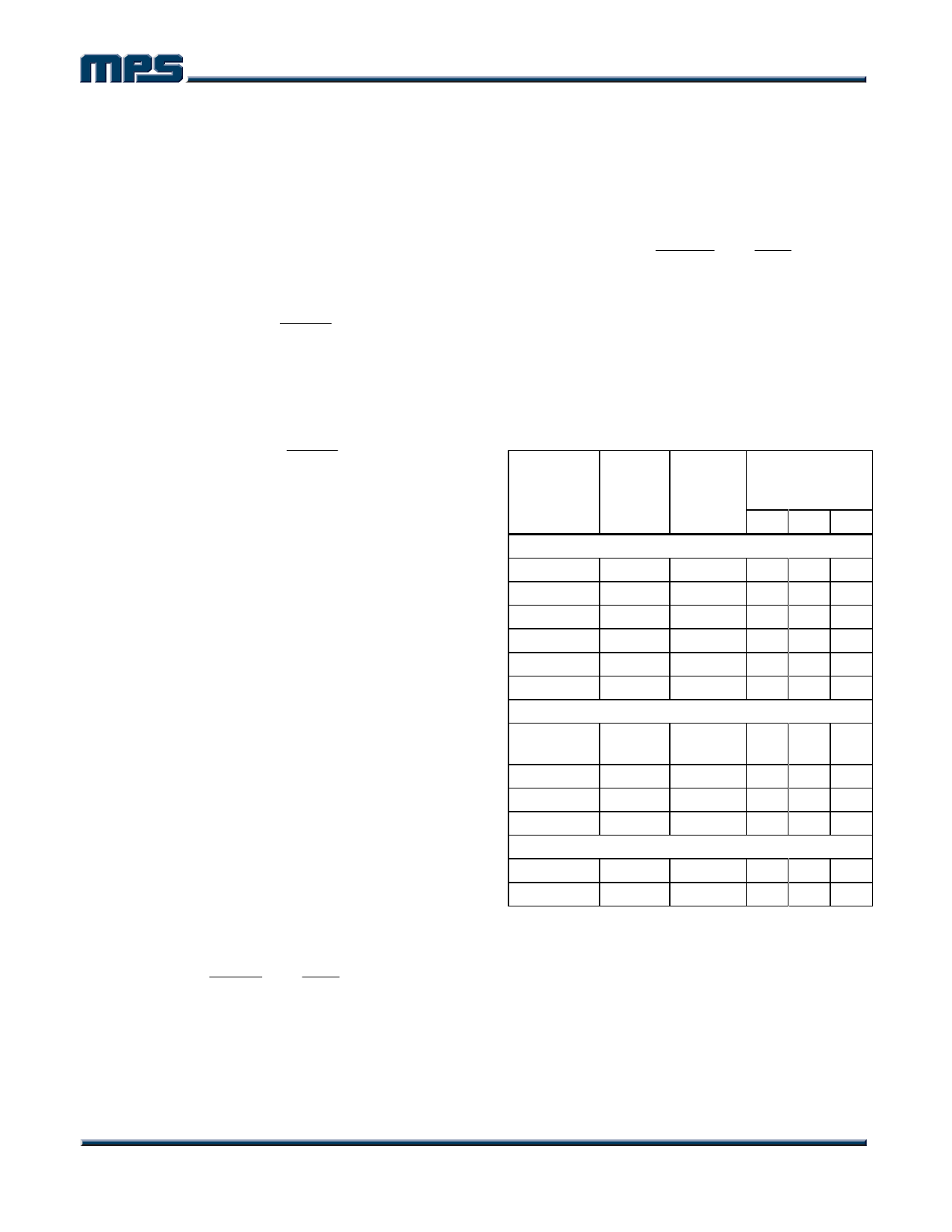
Table 1 lists a number of suitable inductors
from various manufacturers. The choice of
which style inductor to use mainly depends on
the price vs. size requirements and any EMI
requirement.
Table 1—Inductor Selection Guide
Vendor/
Model
Core
Type
Core
Material
Package
Dimensions
(mm)
WL H
Sumida
CR75
Open Ferrite 7.0 7.8 5.5
CDH74 Open Ferrite 7.3 8.0 5.2
CDRH5D28 Shielded Ferrite 5.5 5.7 5.5
CDRH5D28 Shielded Ferrite 5.5 5.7 5.5
CDRH6D28 Shielded Ferrite 6.7 6.7 3.0
CDRH104R Shielded Ferrite 10.1 10.0 3.0
Toko
D53LC
Type A
Shielded Ferrite
5.0 5.0 3.0
D75C Shielded Ferrite 7.6 7.6 5.1
D104C Shielded Ferrite 10.0 10.0 4.3
D10FL Open Ferrite 9.7 1.5 4.0
Coilcraft
DO3308 Open Ferrite 9.4 13.0 3.0
DO3316 Open Ferrite 9.4 13.0 5.1
MP1423 Rev. 1.1
www.MonolithicPower.com
5
1/6/2006
MPS Proprietary Information. Unauthorized Photocopy and Duplication Prohibited.
© 2006 MPS. All Rights Reserved.
Share Link: 