MC44826D データシートの表示(PDF) - Motorola => Freescale
部品番号
コンポーネント説明
一致するリスト
MC44826D Datasheet PDF : 8 Pages
| |||
MC44826
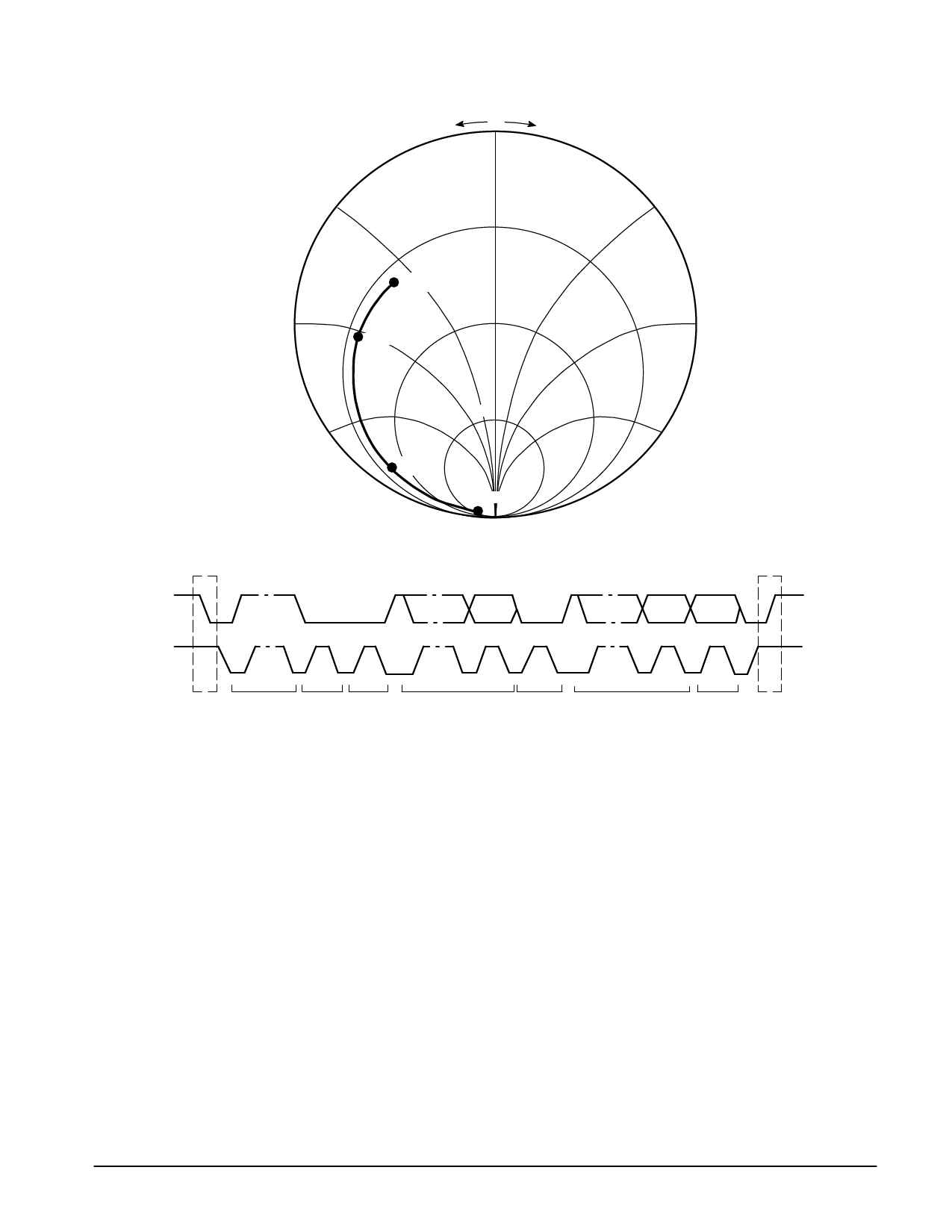
Figure 3. Typical HF Input Impedance
–j +j
0
0.5
0.5
1.3 GHz
ZO = 50 Ω
1
1
1.0 GHz
0.5
1
2
2
2
500 MHz
50 MHz
Figure 4. Complete Data Transfer Process
SDA
SCL
S
1–7
8
9
STA ADDRESS R/W ACK
CA
1–7
8
9
DATA
ACK
1–7
8
DATA
9
P
ACK STO
Data Format and Bus Receiver
The circuit receives the information for tuning and control
via the I2C bus. The incoming information, consisting of a
chip address byte followed by two or four data bytes, is
treated in the I2C bus receiver. The definition of the
permissible bus protocol is shown below:
1_STA CA
2_STA CA
3_STA CA
4_STA CA
CO BA
FM FL
CO BA
FM FL
STO
STO
FM FL
CO BA
STO
STO
STA = Start Condition
STO = Stop Condition
CA = Chip Address Byte
CO = Data Byte for Control Information
BA = Band Information
FM = Data Byte for Frequency Information (MSB’s)
FL = Data Byte for Frequency Information (LSB’s)
Figure 5 shows the five bytes of information that are
needed for circuit operation: there is the chip address, two
bytes of control and band information and two bytes of
frequency information.
After the chip address, two or four data bytes may be
received: if three data bytes are received the third data byte
is ignored.
If five or more data bytes are received the fifth and
following data bytes are ignored and the last acknowledge
pulse is sent at the end of the fourth data byte.
The first and the third data bytes contain a function bit
which allows the IC to distinguish between frequency
information and control plus band information.
Frequency information is preceded by a Logic “0”. If the
function bit is Logic “1” the two following bytes contain control
and band information. The first data byte, shifted after the
chip address, may be byte CO or byte FM.
The two permissible bus protocols with five bytes are
shown in Figure 5.
The Data and Clock inputs (Pins 10 and 11) are high
impedance when the supply voltage VCC1 is between 0 and
5.5 V.
MOTOROLA ANALOG IC DEVICE DATA
5
Share Link: 