OPB780-KIT データシートの表示(PDF) - TT Electronics.
部品番号
コンポーネント説明
一致するリスト
OPB780-KIT Datasheet PDF : 9 Pages
| |||
OPB780-Kit
Color Sensor Evaluation Kit
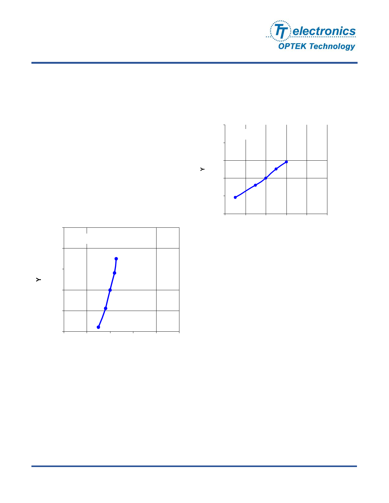
One of the critical parts of the OPB780Z is the LED. It
is very important to understand its characteristics
relative to forward current and temperature. The
below chart shows how the forward current of the LED
changes the Chromatic coordinates.
As can be seen, increasing the forward current of the
LED lowers the “Y” value while minimally changing the
“X” value. The projected most optimum light
(equivalent to sun light at 12 noon with no
contaminates in the air) has both “X” and “Y” chromatic
values of 1/3. Chromatic numbers below 1/3 consist of
more Blue or Green wavelengths and numbers above
1/3 consist of more Red or Yellow wavelengths. As
can be seen a forward current of approximately 4 mA
would provide the most optimum “Y” value.
Forward Current vs Chromaticity
Coordinate
0.35
TA = 25° C
0.34
1 mA
0.33
5 mA
0.32
20 mA
0.31
50 mA
0.30
100 mA
0.29 0.30 0.31 0.32 0.33 0.34
X
Ambient Temperature vs Chromaticity
Coordinate
0.35
IFP = 20 mA
0.34
0.33
-30° C
0° C
0.32
25° C
50° C
0.31
85° C
0.30
0.29 0.30 0.31 0.32 0.33 0.34
X
The graphs show the change in chromaticity vs
temperature. As the temperature reduces the “X”
value moves closer toward the optimum (1/3) value.
In conclusion, the lower the forward current and the
cooler the temperature, the closer the LED transmits to
the optimum chromatic values of “X”=1/3 and “Y”=1/3.
In order to provide sufficient light levels and the best
color resolution, the white LED should be driven with
at least 20 mA of forward current and operated at
room temperatures (approx. 25°C). These conditions
result in chromatic ranges of about “X”=0.31 and
“Y”=0.32.
The responsivity of the each diode group is dependent
on the angular position of the device to the object.
The graphs showing the typical variance of the Output
frequency of the device vs both Azmuth (twist) and
Zenith (bend) are shown in the two graphs.
OPTEK reserves the right to make changes at any time in order to improve design and to supply the best product possible.
Issue A.2 11/09
Page 4 of 9
OPTEK Technology Inc. — 1645 Wallace Drive, Carrollton, Texas 75006
Phone: (972) 323-2200 or (800) 341-4747
FAX: (972) 323-2396 sensors@optekinc.com www.optekinc.com
Share Link: 