PS9715 データシートの表示(PDF) - California Eastern Laboratories.
部品番号
コンポーネント説明
一致するリスト
PS9715
California Eastern Laboratories.

PS9715 Datasheet PDF : 6 Pages
| |||
PS9715
ELECTRICAL CHARACTERISTICS (TA = 0 to +85°C, Unless otherwise specified), Continued
PART NUMBER
PS9715
SYMBOL
PARAMETERS
UNITS
MIN
TYP
MAX
| tPHL – tPLH | Pulse Width Distortion, (PWD)3, VCC = 5 V, IF = 7.5 mA
ns
CMH
Common Mode Transient Immunity at High Level Output4,
VCC = 5 V, TA = 25°C, IF = 0 mA, VO (MIN) = 2 V, VCM = 1 kV
kV/µs
10
CML
Common Mode Transient Immunity at Low Level Output4,
kV/µs
10
VCC = 5 V, TA = 25°C, IF = 7.5 mA, VO (MAX) = 0.8 V, VCM = 1 kV
7
50
20
20
Notes:
1. Typical values at TA = 25°C.
2. Because a high level output current (IOH) of 300 µA or more may be output when the temperature is 0°C or less and when VCC is around 3 to
4 V, it is important to confirm the characteristics (operation with the power supply on and off) during design, before using the device.
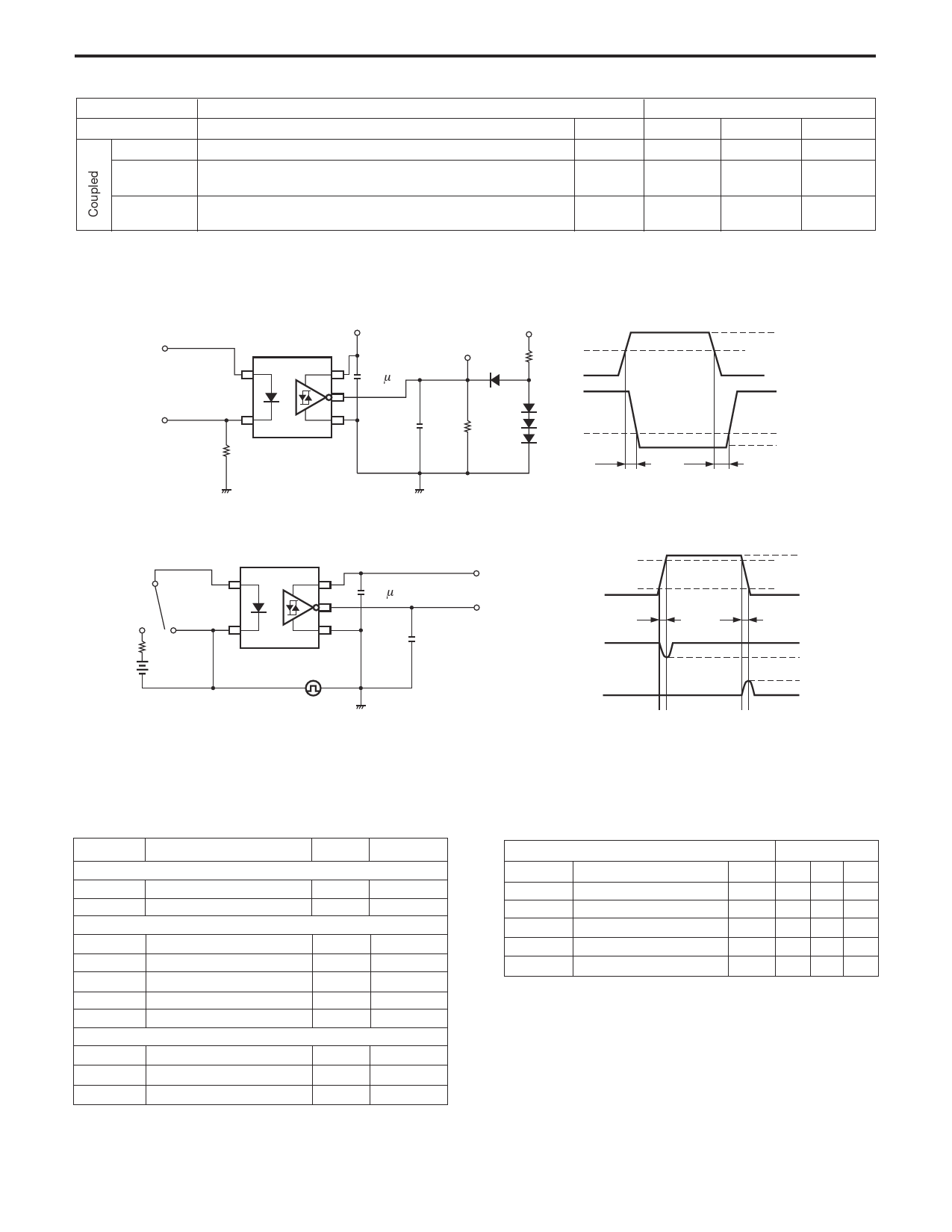
3. Test Circuit for Propagation delay time
Pulse input (IF)
(PW = 500 ns,
Duty cycle = 1/2)
VCC = 5 V
0.1 µ F
VCC = 5 V
VO (monitor)
Input
1.3 kΩ
IF (ON)
50% IF (ON)
VOH
Input
(monitor)
47 Ω
CL =
30 pF 2.5 kΩ
Output
tPHL
tPLH
1.5 V
VOL
CL includes probe and stray wiring capacitance.
4.Test Circuit for common mode transient immunity
SW IF
0.1 µF
VCC = 5 V
VCM 90%
1 kV
10%
0V
VO (Monitor)
tr
tf
CL = 15 pF
VCM
VO
(IF = 0 mA)
VO
(IF = 7.5 mA)
VOH
2V
0.8 V
VOL
CL includes probe and stray wiring capacitance.
USAGE CAUTIONS
1. This device is ESD sensitive.
2. Bypass capacitor of more than 0.1 µF is used between VCC and GND near device. Also, ensure that the distance between the leads of the
photocoupler and capactor is no more than 10 mm.
RECOMMENDED
ABSOLUTE MAXIMUM RATINGS1 (TA = 25°C)
OPERATING CONDITIONS
SYMBOLS
Diode
IF
VR
Detector
VCC
VO
IOH
IOL
PC
Coupled
BV
TOP
TSTG
PARAMETERS
Forward Current
Reverse Voltage
Supply Voltage
Output Voltage
High level Output Current2
Low level Output Current2
Power Dissipation2,3
Isolation Voltage4
Operating Temperature
Storage Temperature
UNITS RATINGS
mA
30
V
5
V
7
V
7
mA
-5
mA
13
mW
130
Vr.m.s.
°C
°C
2500
-40 to +85
-55 to +125
PART NUMBER
SYMBOLS
PARAMETERS
IFH
High Level Input Current
IFL
Low Level Input Current
VCC
Supply Voltage
N
TTL(loads)
TA
Operating Temperature
PS9715
UNITS MIN TYP MAX
mA 7.5
12.5
µA 0
250
V 4.5 5.0 5.5
3
°C 0
+85
Notes:
1. Operation in excess of any one of these parameters may result
in permanent damage.
2. TA = -40 to +85°C, Applies to output pin Vo and power supply pin
VCC.
4. AC voltage for 1 minute at TA = 25 °C, RH = 60% between input
and output.
Share Link: