M54HC365F1R データシートの表示(PDF) - STMicroelectronics
部品番号
コンポーネント説明
一致するリスト
M54HC365F1R Datasheet PDF : 11 Pages
| |||
M54/M74HC365/366
AC ELECTRICAL CHARACTERISTICS (CL = 50 pF, Input tr = tf = 6 ns)
Symbol
Parameter
Test Conditions
VCC CL
(V) (pF)
TA = 25 oC
54HC and 74HC
Value
-40 to 85 oC -55 to 125 oC Unit
74HC
54HC
Min. Typ. Max. Min. Max. Min. Max.
tTLH Output Transition 2.0
tTHL Time
4.5 50
25 60
75
90
7
12
15
18
ns
6.0
6
10
13
15
tPLH Propagation
tPHL Delay Time
2.0
4.5 50
38 90
12 18
115
135
23
27
ns
6.0
10 15
20
23
2.0
4.5 150
51 130
165
195
17 26
33
39
ns
6.0
14 22
28
33
tPZL Output Enable
2.0
64 130
165
195
tPZH Time
4.5 50 RL = 1 KΩ
16 26
33
39
ns
6.0
14 22
28
33
2.0
76 150
190
225
4.5 150 RL = 1 KΩ
19 30
38
45
ns
6.0
16 26
32
38
tPLZ Output Disable
2.0
42 130
165
195
tPHZ Time
4.5 50 RL = 1 KΩ
18 26
33
39
ns
6.0
15 22
28
33
CIN
CPD (*)
Input Capacitance
Power Dissipation
Capacitance
for HC365
for HC366
5
10
10
10 pF
27
25
pF
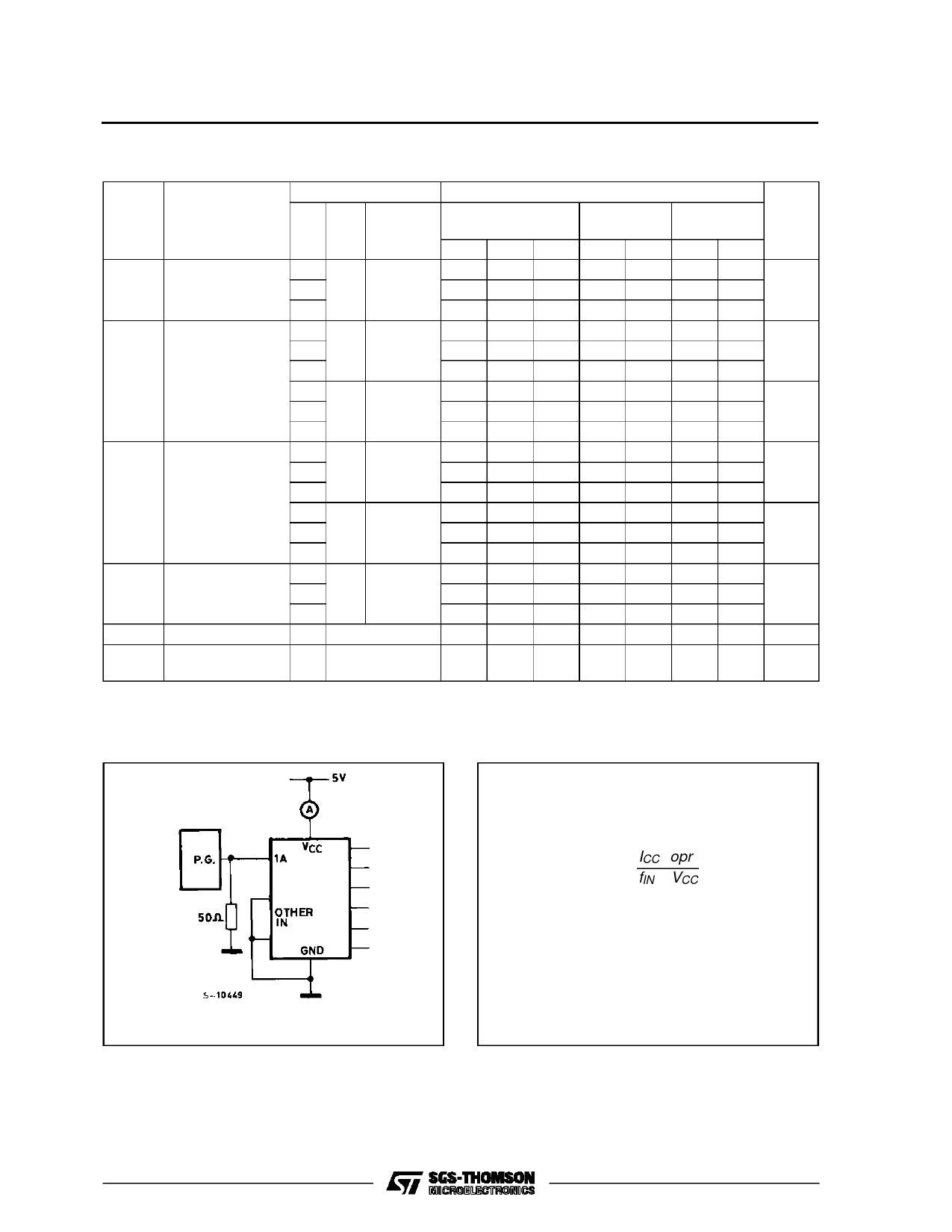
(*) CPD is defined as the value of the IC’s internal equivalent capacitance which is calculated from the operating current consumption without load.
(Refer to Test Circuit). Average operting current can be obtained by the following equation. ICC(opr) = CPD •VCC •fIN + ICC/6 (per Gate)
TEST CIRCUIT ICC (Opr.)
CPD CALCULATION
CPD is to be calculated with the following
formula by using the measured value of
ICC (opr.) in the test circuit opposite.
CPD
=
ICC (opr)
fIN × VCC
In determining the typical value of CPD a
relatvely high frequency of 1 MHz was ap-
plied to fIN, in order to eliminate any error
caused by the quiescent supply current.
INPUT WAVEFORM IS THE SAME AS THAT IN CASE OF
SWITCHING CHARACTERISTICS TEST.
5/11
Share Link: 