EL4585 データシートの表示(PDF) - Renesas Electronics
部品番号
コンポーネント説明
一致するリスト
EL4585 Datasheet PDF : 15 Pages
| |||
EL4585
positive when EXT DIV lags HSYNC.) The resistance needed
will depend on VCO design or VCXO module selection.
Applications Information
Choosing External Components
1. To choose LC VCO components, first pick the desired
operating frequency. For our example we will use
28.636MHz, with an HSYNC frequency of 15.734kHz.
2. Choose a reasonable inductor value (1µ to 5µH works
well). We choose 3.3µH.
3. Calculate CT needed to produce FOSC.
FOSC
=
-----------1-----------
2 LCT
CT = 4--------2--1-F----2---L-- = -4-------2------2---8---.--6---3----6---e---1-6----2--------3---.--3----e-----–----6---- = 9.4pF
(EQ. 1)
4. From the varactor data sheet find CV @ 2.5V, the desired
lock voltage. CV=23pF for our SMV1204-12 for example.
5. C2 should be about 10CV, so we choose C2=220pF for
our example.
6. Calculate C1. Since:
CT = ---C----1----C----2-------+----C----C-1---C1----C2----CV----V----+-------C----2----C----V-----
(EQ. 2)
then:
C1 = ---C-----2---C----V--------–---C----C2----C2----CT----CT----V---–-------C-----T----C----V-----
(EQ. 3)
For our example, C1=17pF. (A trim capacitor may be used
for fine tuning.) Examples for each frequency using the
internal divider is shown in Figure 8.
FIGURE 8. TYPICAL LC VCO
LC VCO COMPONENT VALUES (APPROXIMATE) (Note)
FREQUENCY
L1
C1
C2
(MHz)
(µH)
(pF)
(pF)
26.602
3.3
22
220
27.0
3.3
21
220
29.5
2.7
22
220
35.468
2.2
16
220
21.476
4.7
26
220
24.546
3.9
22
220
28.636
3.3
17
220
NOTE: Use shielded inductors for optimum performance.
FN7175 Rev 4.00
September 3, 2009
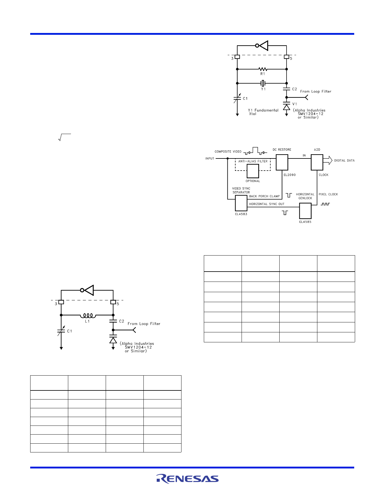
FIGURE 9. TYPICAL XTAL VCO
Typical Application
Horizontal genlock provides clock for an analog-to-digital
converter, digitizing analog video.
XTAL VCO COMPONENT VALUES (APPROXIMATE)
FREQUENCY
(MHz)
26.602
R1
(k)
300
C1
C2
(pF)
(µF)
15
0.001
27.0
300
15
0.001
29.5
300
15
0.001
35.468
300
15
0.001
21.476
300
15
0.001
24.546
300
15
0.001
28.636
300
15
0.001
The oscillators are arranged as Colpitts oscillators
(see Figure 8), and the structure is redrawn here to emphasize
the split capacitance used in a Colpitts oscillator. It should be
noted that this oscillator configuration is just one of literally
hundreds possible, and the configuration shown here does not
necessarily represent the best solution for all applications.
Crystal manufacturers are very informative sources on the
design and use of oscillators in a wide variety of applications,
and the reader is encouraged to become familiar with them.
Page 9 of 15
Share Link: 