FM50(2002) データシートの表示(PDF) - Fairchild Semiconductor
部品番号
コンポーネント説明
一致するリスト
FM50 Datasheet PDF : 8 Pages
| |||
PRODUCT SPECIFICATION
FM50
Applications Information
Although the FM50 is a simple device, care must be taken to
ensure that temperature is measured accurately. There are
two major sources of errors:
3. Voltage errors.
4. Thermal Delay Errors.
5. Location errors
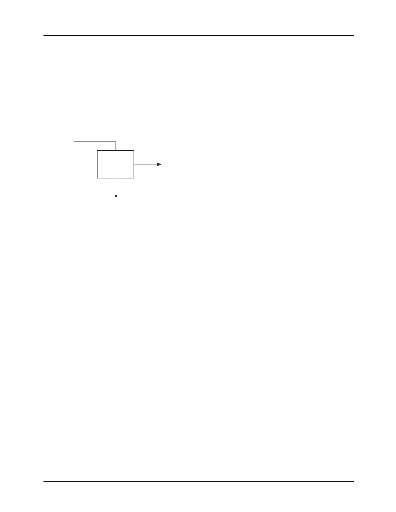
Voltage Errors
VDD
FM50
VOUT
GND(power)
GND(sense)
Figure 4. Recommended Electrical Connections
A Kelvin connection is recommended to avoid errors due to
voltage drops in the ground connections. Although the
typical 130µA supply current draw of the FM50 will only
cause a 130µV error if the series resistance is 1Ω, a 100 mA
current supply to adjacent circuits can cause a 10mV drop
across 100mΩ (10mΩ is a typical value for soldered joints or
contact resistance), leading to a 1°C error. For this reason,
the FM50 should be Kelvin connected as shown in Figure 4.
Thermal Delay Errors
For measurement accuracy of the order of tenths of 1°C,
adequate settling time must be allowed. For a typical circuit
board installation, 15 minutes should be allowed to elapse
following reading of temperature within 1 - 2°C of the
expected final value. Once VOUT has ceased to slew and
is stable (with or without about ±0.1°C noise) for about 5
minutes, temperature can be calculated.
Location Errors
Position is another source of error. Even within a controlled
thermal environment, changing location by a few inches can
lead to errors of several tenths of 1°C
Mounting
The FM50 can be easily mounted by gluing or cementing it
to a surface. In this case, its temperature will be within about
0.2°C of the temperature of the surface it is attached to if the
ambient air temperature is almost the same as the surface
temperature. If the air temperature is much higher or lower
than the surface temperature, the actual temperature of the
FM50 die will be at an intermediate temperature between the
surface temperature and the air temperature.
To ensure good thermal conductivity, the backside of the
FM50 die is directly attached to the GND pin. The lands and
traces to the FM50 will, of course, be part of the printed
circuit board, which is the object whose temperature is being
measured. These printed circuit board lands and traces will
not cause the FM50’s temperature to deviate from the
desired temperature.
Alternatively, the FM50 can be mounted inside a sealed-end
metal tube, and can then be dipped into a bath or screwed
into a threaded hole in a tank. As with any IC, the FM50 and
accompanying wiring and circuits must be kept insulated and
dry to avoid leakage and corrosion. This is especially true if
the circuit may operate at cold temperatures where conden-
sation can occur. Printed-circuit coatings and varnishes such
as Humiseal and epoxy paint or dips can be used to ensure
that moisture cannot corrode the FM50 or its connections.
REV. 1.0.8 9/12/02
5
Share Link: 