CDB61884 データシートの表示(PDF) - Cirrus Logic
部品番号
コンポーネント説明
一致するリスト
CDB61884 Datasheet PDF : 22 Pages
| |||
CDB61884
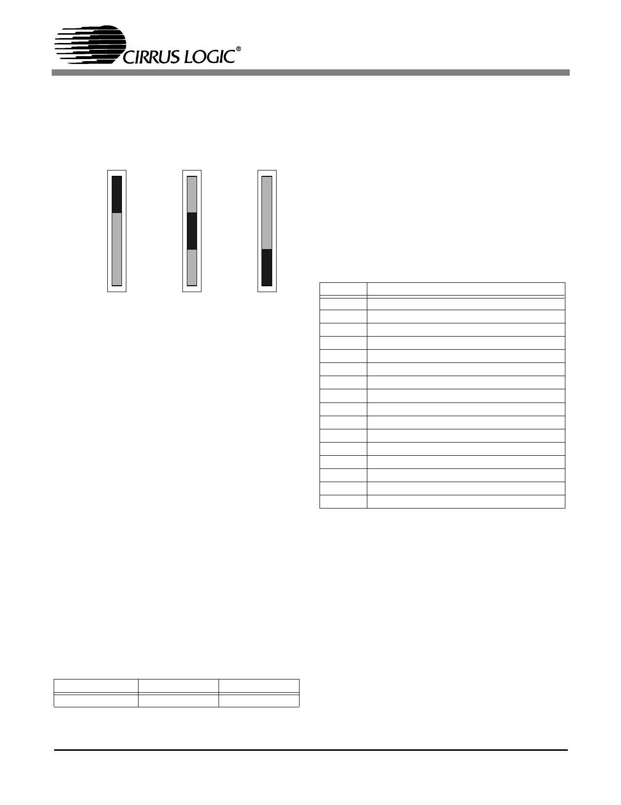
2.3 Operating Mode Selection
The operating mode for the CS61884 can be select-
ed by setting switch S15 to one of the positions
shown in Figure 4.
S15
S15
S15
Hardware
Hardware
Hardware
Serial Host
Serial Host
Serial Host
Parallel Host
Parallel Host
Parallel Host
MODE
Selects
Hardware Mode
MODE
Selects Serial
Host Mode
MODE
Selects Parallel
Host Mode
Figure 4. Hardware/Host Mode Selection
2.4 Line Interface Connections
In both hardware and host modes, the receive line
signals (RTIP/RRING) are connected to the bind-
ing post labeled RXT 0-7 and RXR 0-7. The line
signals from the binding posts are coupled to the
device through two octal transformers (T1 and T9).
The receivers of the device use external resistors to
match the line impedance. These resistors are sock-
eted for ease in changing the line impedance, for in-
ternal or external line impedance matching. During
internal line impedance matching mode, the resis-
tor values are the same (15 Ω) for all modes of op-
eration: E1 75 Ω, E1 120 Ω or T1/J1 100 Ω. During
external line impedance matching mode the receiv-
er resistors need to be change to the values shown
in Table 1.
Table 1. External Impedance Resistor Values
T1/J1 100 Ω
12.5Ω
E1 75 Ω
9.31Ω
E1 120 Ω
15Ω
The jumpers listed in Table 2 are used to place or
bypass 1 KΩ protection resistors in series with the
receive line signals (RTIP/RRING). These resis-
tors are used for receiver protection while in exter-
nal line impedance matching mode and should not
be used during internal line impedance matching
mode. To place the 1 KΩ resistors in series with the
receive line signals, remove the short blocks from
each of the jumpers described in Table 2. To by-
pass the 1 KΩ resistors, place a short block on each
jumper shown in Table 2.
Table 2. Protection Resistor Selection
Jumper
J29
J30
J37
J38
J46
J47
J54
J55
J65
J66
J73
J74
J81
J82
J89
J90
Description
Channel 0 RRING signal
Channel 0 RTIP Signal
Channel 1 RTIP Signal
Channel 1 RRING Signal
Channel 2 RRING Signal
Channel 2 RTIP Signal
Channel 3 RTIP Signal
Channel 3 RRING Signal
Channel 4 RRING Signal
Channel 4 RTIP Signal
Channel 5 RTIP Signal
Channel 5 RRING Signal
Channel 6 RRING Signal
Channel 6 RTIP Signal
Channel 7 RTIP Signal
Channel 7 RRING Signal
The transmit line signals (TTIP/TRING) from the
device are coupled to the line binding post (TXT 0-
7 and TXR 0-7) through two octal transformers (T1
and T9). External protection circuitry such as di-
odes or chokes are recommended for protection.
For further information on line protection refer to
Application Note AN34, “Secondary Line Protec-
tion for T1 and E1 Line Cards” (AN34REV1 SEP
'94).
2.5 TXOE Selection
Jumper J23 is used to enable or High-Z all eight
transmitters in both hardware and host mode. A
shorting block on Jumper J23 places all the trans-
6
DS485DB1
Share Link: 