MAX11503 データシートの表示(PDF) - Maxim Integrated
部品番号
コンポーネント説明
一致するリスト
MAX11503 Datasheet PDF : 8 Pages
| |||
Video Y/C Summer with
Driver and Chroma Mute
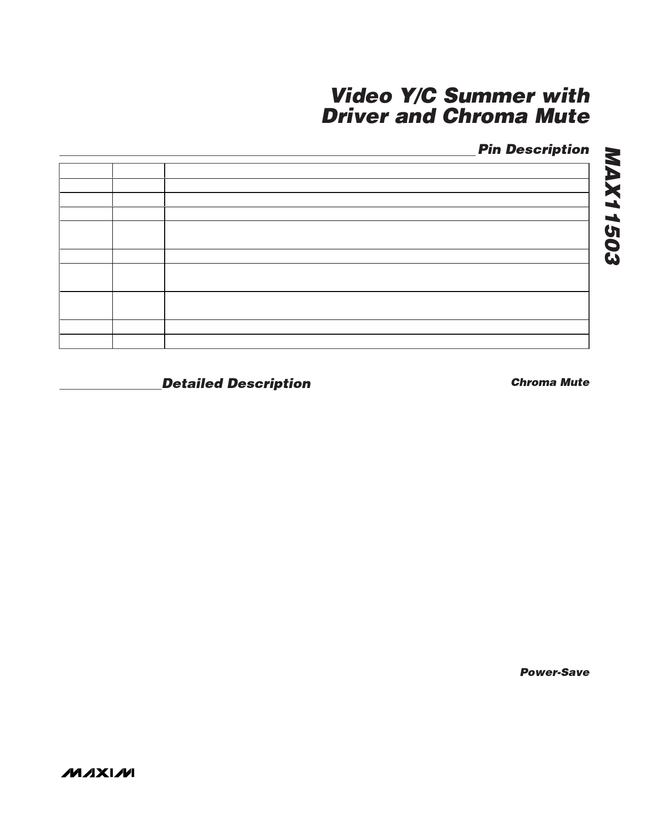
Pin Description
PIN
NAME
1
YIN Luma Input
2
GND Ground
3
OUT Video Out
FUNCTION
4
SAG
Sag Correction Input. Connect to OUT when AC- or DC-coupling video output. See Figure 1 to determine
capacitor value and circuit.
5
VCC Power Supply. Bypass to GND with 0.1µF and 1µF capacitors.
6
PSAVE Active-Low Power-Save Logic Input. Connect PSAVE to VCC for normal operation. Drive low to put device
into a low-power consumption mode.
7
CMUTE
Chroma Mute Logic Input. Connect CMUTE to ground for normal operation. Drive high to disable the
chroma buffer.
8
CIN Chroma Input
EP
—
Exposed Pad. Connect EP to ground.
Detailed Description
The MAX11503 is a low-power video amplifier with a
Y/C summer and chroma mute. The device accepts an
S-video or Y/C input and sums the luma (Y) and chroma
(C) signals into a composite CVBS signal which can be
connected directly to a TV monitor. The MAX11503 drives
two terminated 75Ω video coax cables.
The MAX11503 features chroma mute, power save, and
SAG correction. Chroma mute disables the chroma
buffer. If the device is used to combine Y and C signals
in a camera application, chroma mute may be used in
low-light situations. This removes all chroma including
burst which causes a downstream composite video
decoder to interpret the video signal as luminance only,
thus improving image quality. Power-save puts the
device into a low-power consumption mode. SAG
correction allows small output capacitors to be used
in AC-coupled output applications.
The MAX11503 has a transparent clamp at YIN, allow-
ing the luma input to be AC- or DC-coupled. If the luma
input is DC-coupled, the sync tip must be at ground
and the video signal must be 1VP-P. For low-supply
voltages, ensure that the DC level of the input is low
enough to avoid clipping at the output. If the luma input
is AC-coupled, the clamp adjusts the luma signal’s
sync tip to ground at YIN. Use an AC-coupling capacitor
of 0.1µF.
The MAX11503 has an internal AC-coupling capacitor
at CIN, allowing the chroma input to be coupled directly
to CIN.
Chroma Mute
In applications using cameras that output composite
video, the video is always decoded by a downstream
composite decoder in a monitor or for further video
processing.
In low-light conditions, the camera video signal
becomes noisy. The high-frequency (less visible mono-
chrome) noise from the camera is transformed to low-
frequency highly visible colored noise by the normal
encode and decode blocks of composite video pro-
cessing. This is caused when the chroma information is
encoded onto a high-frequency subcarrier, mixed with
the luminance and the decoded. First, high-frequency
noise near the color subcarrier is down-converted to
low-frequency noise. Second, chroma separation by
comb filtering removes luminance noise, but correlates
the noise in phase with the chroma to become vertical
lines. These two effects cause highly visible and objec-
tional color noise. Hence, using a purely monochrome
signal is better looking than a color signal.
When pulled high, the chroma mute input disables all
chroma and burst and the device outputs a mono-
chrome video signal. This causes the downstream
decoder to recognize the video signal as monochrome.
Power-Save
Asserting PSAVE logic low puts the device into a
power-down mode, reducing the supply current to
0.5µA and minimizing power consumption. Connect
PSAVE to VCC for normal operation.
_______________________________________________________________________________________ 5
Share Link: 