RTL8111E-VL-CG データシートの表示(PDF) - Realtek Semiconductor
部品番号
コンポーネント説明
一致するリスト
RTL8111E-VL-CG
Realtek Semiconductor

RTL8111E-VL-CG Datasheet PDF : 37 Pages
| |||
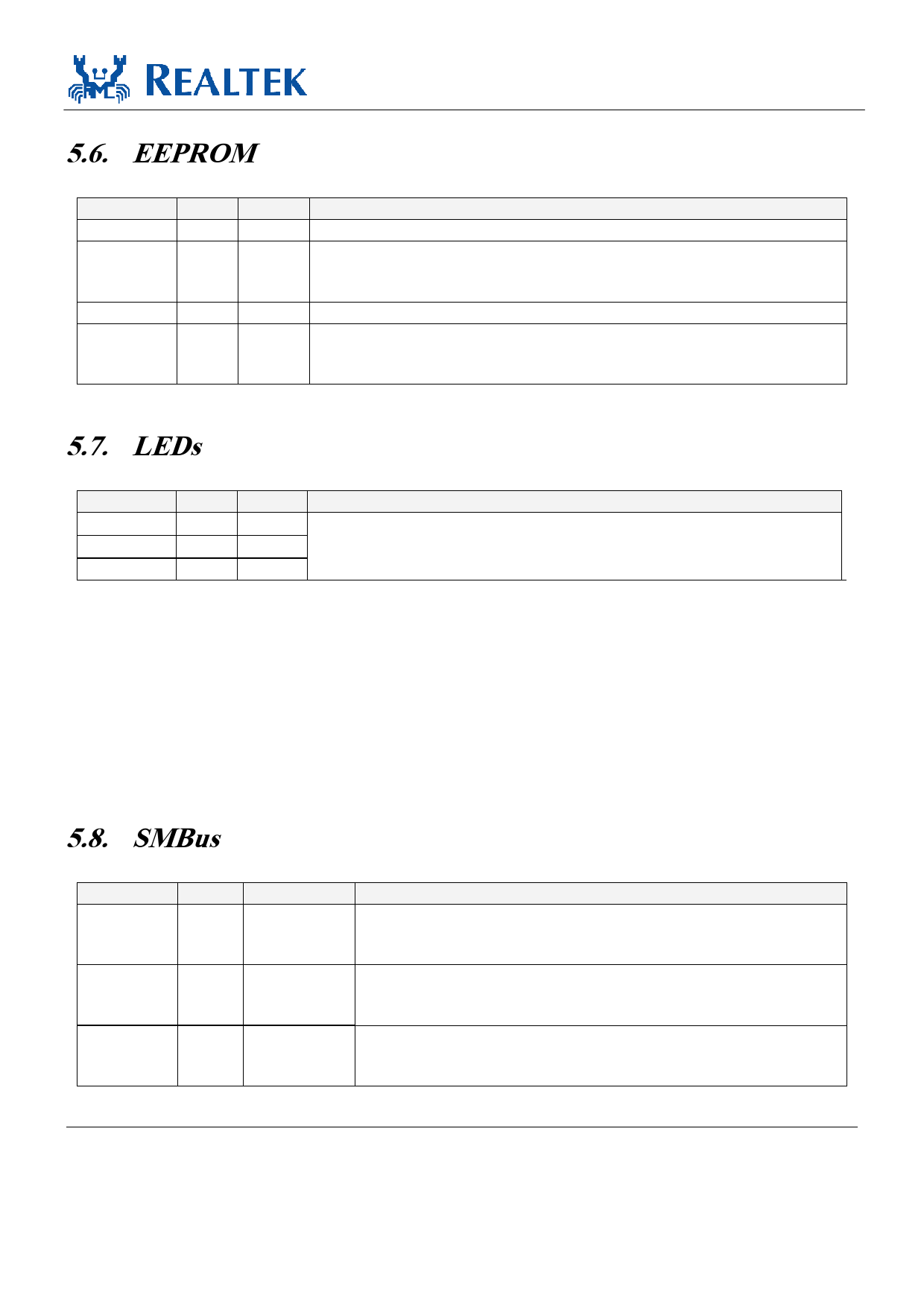
5.6. EEPROM
Symbol
EESK
EEDI
EEDO
EECS
Type
O
O/I
I
O
Pin No
37
32
31
30
Table 6. EEPROM
Description
Serial Data Clock.
EEDI: Output to serial data input pin of EEPROM.
Refer to the reference schematic for strapping pin information.
All strapping pins are power-on-latch pins.
Input from Serial Data Output Pin of EEPROM.
EECS: EEPROM Chip Select.
Refer to the reference schematic for strapping pin information.
All strapping pins are power-on-latch pins.
RTL8111E
Datasheet
5.7. LEDs
Table 7. LEDs
Symbol
Type Pin No Description
LED0
O
40 See section 6.2.6 Customizable LED Configuration, page 12 for details.
LED1
O
37
LED3
O
31
Note 1: During power down mode, the LED signals are logic high.
Note 2: LEDS1-0’s initial value comes from the EEPROM. If there is no EEPROM, the default value of the
(LEDS1, LEDS0)=(1, 1).
When implementing dual color LEDs and EEPROM at the same time:
Pin31 and Pin37 of the RTL8111E are shared pins. Follow the RTLRTL8111E reference design (version
1.00 or later) to select these 2 pins for a dual-color LED circuit. Otherwise, the RTLRTL8111E EEPROM
may not function.
5.8. SMBus
Symbol
SMBCLK
Type
O/D
SMBDATA
O/D
SMBALERT O/D
Pin No
14
15
38
Table 8. SMBus
Description
SMBus Clock.
Refer to the reference schematic for strapping pin information.
All strapping pins are power-on-latch pins.
SMBus Data.
Refer to the reference schematic for strapping pin information.
All strapping pins are power-on-latch pins.
SMBus Alert.
Refer to the reference schematic for strapping pin information.
All strapping pins are power-on-latch pins.
Integrated Gigabit Ethernet Controller for PCI Express
7
Track ID: JATR-2265-11 Rev. 1.1
Share Link: