AQV210HL データシートの表示(PDF) - Matsushita Electric Works
部品番号
コンポーネント説明
一致するリスト
AQV210HL
Matsushita Electric Works

AQV210HL Datasheet PDF : 6 Pages
| |||
AQV210HL
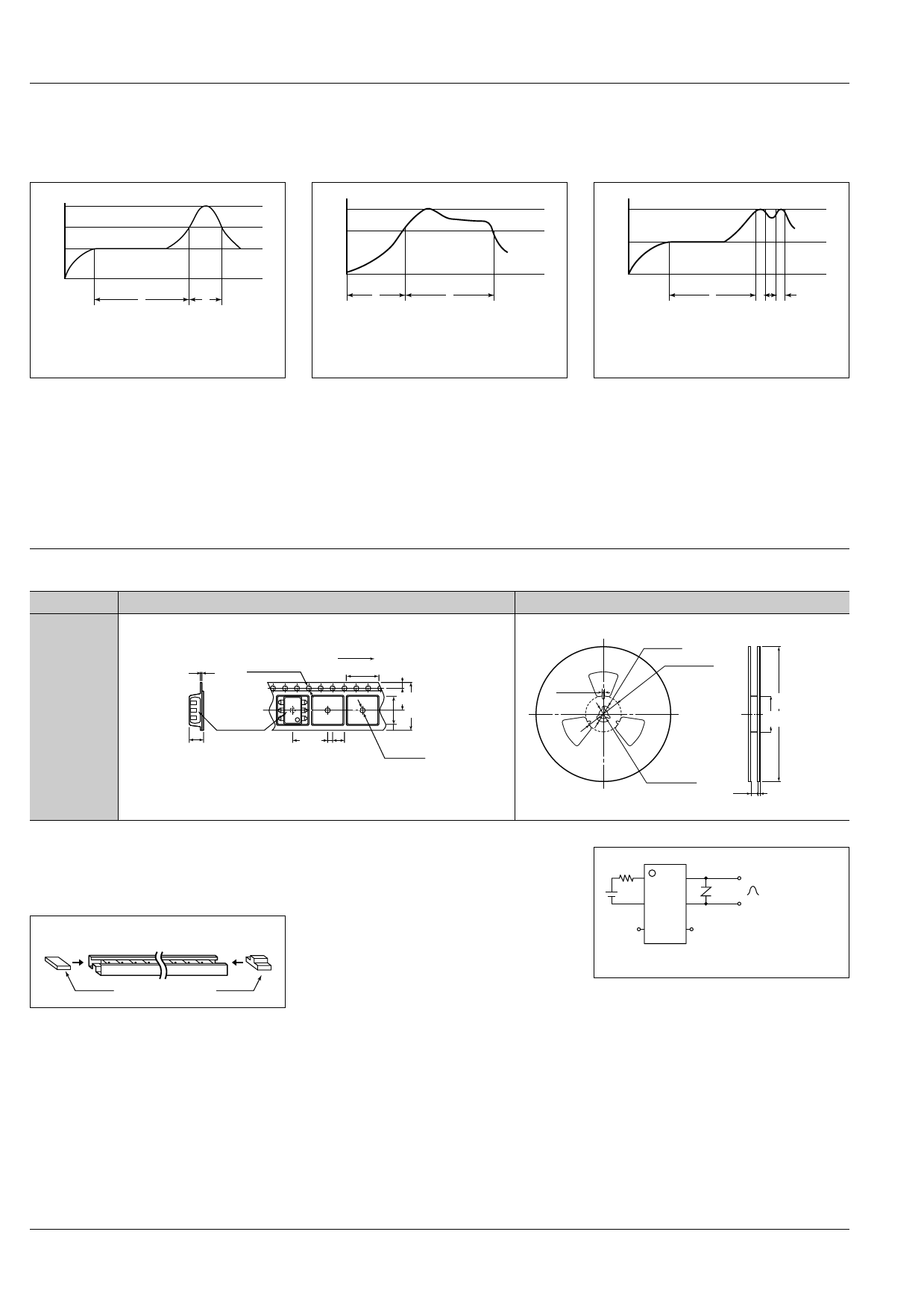
8. Soldering
1) When soldering PC board terminals,
keep soldering time to within 10 s at
260°C 500°F.
(1) IR (Infrared reflow) soldering method
T3
T2
T1
2) When soldering surface-mount termi-
nals, the following conditions are recom-
mended.
(2) Vapor phase soldering method
T2
T1
(3) Double wave soldering method
T2
T1
t1
t2
T1 = 155 to 165°C 311 to 329°F
T2 = 180°C 200°C 356 to 392°F
T3 = 245°C 473°F or less
t1 = 120 s or less
t2 = 30 s or less
(4) Soldering iron method
Tip temperature: 280 to 300°C 536 to
572°F
Wattage: 30 to 60 W
Soldering time: within 5 s
t1
t2
T1 = 180 to 200°C 366 to 392°F
T2 = 215°C 419°F or less
t1 = 40 s
t2 = 90 s or less (40 s or less for SOP type)
t1
t2 t3
T1 = 155 to 165°C 311 to 329°F
T2 = 260°C 500°F or less
t1 = 60 s or less
t2+t3 = 5 s or less
(5) Others
Check mounting conditions before using
other soldering methods (hot-air, hot
plate, pulse heater, etc.)
• The temperature profile indicates the
temperature of the soldered terminal on
the surface of the PC board.
The ambient temperature may increase
excessively. Check the temperature under
mounting conditions.
• The conditions for the infrared reflow sol-
dering apply when preheating using the
VPS method.
9. The following shows the packaging format
1) Tape and reel
Type
Tape dimensions
Dimensions of paper tape reel
6-pin SMD
type
0.4±0.05
.016±.002
Tractor feed holes
1.5
+0.1
–0
dia.
.059
+.004
–0
dia.
Direction of picking
10.1±0.1
.400±.004
1.75±0.1
.069±.004
Device mounted
on tape
7.5±0.1
.295±.004
16±0.3
.630±.012
4.5±0.3
.177±.012
12±0.1
4±0.1
.472±.0042±0.1 .157±.004
9.2±0.1
.362±.004
1.6±0.1 dia.
.079±.004
.063±.004 dia.
(1) When picked from 1/2/3-pin side: Part No. AQVrrrAX (Shown above)
(2) When picked from 4/5/6-pin side: Part No. AQVrrrAZ
2±0.5
.079±.020
21±0.8
.827±.031
80±1 dia.
3.150±.039 dia.
300±2 dia.
11.811±.079 dia.
80±1 dia.
3.150±.039 dia.
13±0.5 dia.
.512±.020 dia.
17.5±2.0
.689±.079
2±0.5
.079±.020
2) Tube
Devices are packaged in a tube so pin No.
1 is on the stopper B side. Observe cor-
rect orientation when mounting them on
PC boards.
(DIP, SMD type)
StopperB
StopperA
10. Transportation and storage
1) Extreme vibration during transport will
warp the lead or damage the relay. Han-
dle the outer and inner boxes with care.
2) Storage under extreme conditions will
cause soldering degradation, external ap-
pearance defects, and deterioration of the
characteristics. The following storage
conditions are recommended:
• Temperature: 0 to 45°C 32 to 113°F
• Humidity: Less than 70% R.H.
• Atomosphere: No harmful gasses such
as sulfurous acid gas, minimal dust.
11. Current limit function (output cur-
rent control)
1) Current limit function aims to increase
resistance to surges when the switch is
turned on. Before using this function,
connect the varistor to the output as
shown in the figure below.
1
6
2
Varistor
5
Surge:
10 × 160 µs, 1.6 KV
3
4
* Set the varistor voltage to 150 V or less.
2) The current limit function capability can
be lost if used longer than the specified
time. Be sure to set the output loss to the
max. rate.
6
Share Link: