MC33197D データシートの表示(PDF) - Motorola => Freescale
部品番号
コンポーネント説明
一致するリスト
MC33197D Datasheet PDF : 8 Pages
| |||
Vbb
Int
Switch
Gnd
MC33197
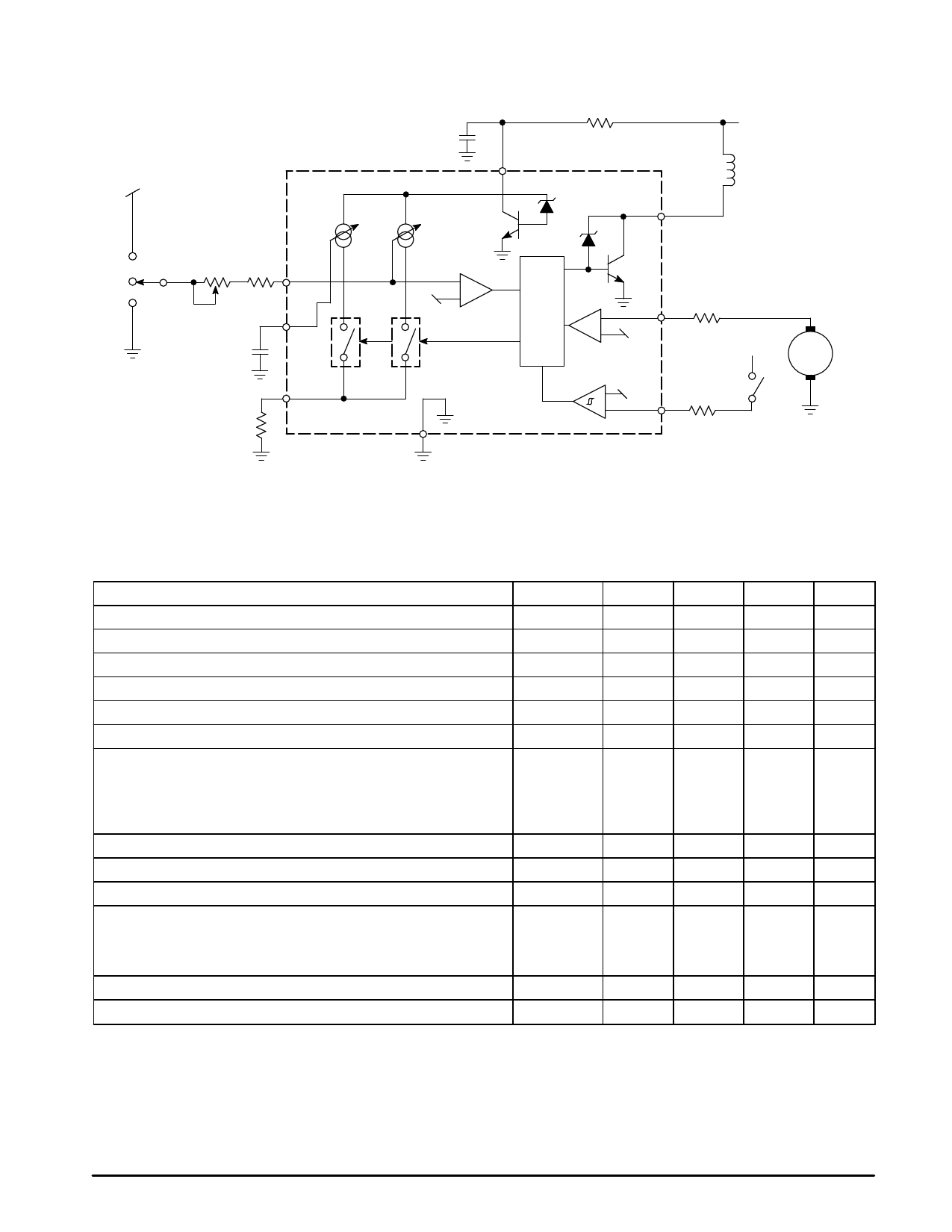
Representative Block Diagram
C1
Variable Current Sources
R1
VCC
MC33197
Out
Vbb
Wiper
Motor
Relay
R1 = 220 Ω
R2 = 22 kΩ
R3 = 1.5 to 22 kΩ
R4 = 4.7 kΩ
R5 = 4.7 kΩ
C1 = 47 µF
C2 = 100 nF
R3
INT
Osc2
C2
Osc1
R2
Ref
Input
Logic
Comparator
Input Comparator
Gnd
with Hysteresis
W/W
Ref
Ref
CONT
Water Pump Motor
R4
Vbb
M
R5
Cont Switch
This device contains 390 active transistors.
ELECTRICAL CHARACTERISTICS (–40°C ≤ TA ≤ +125°C, 8.0 V ≤ VCC ≤ 16 V, unless otherwise noted. Typical values reflect approxi-
mate mean at TA = 25°C with VCC = 14 V at the time of initial device characterization.)
Characteristic
Symbol
Min
Typ
Max
Unit
Functional Supply Voltage Range
Operating Supply Voltage Range
Standby Supply Current (VCC = 16 V, R2 = 68 k)
Supply Current INT Active (R3 = 2.5 k)
Supply Current Relay “On” (R2 = 68 k)
Supply Current INT and Relay “On” (R2 = 68 k, R3 = 2.5 k)
Oscillator Variations with Supply Voltage and Temperature (excluding
external component tolerances, C2 = 100 nF polyester capacitor)
(Notes 1 & 2)
10 V ≤ Vbb ≤ 16 V
8.0 V ≤ Vbb ≤ 16 V
Relay Resistance
Output Voltage (Iout = 200 mA)
Output Clamp Voltage (Iout = 20 mA)
Oscillator Period Coefficient (TA = 25°C)
Vbb = 13 V (Note 3)
Vbb = 13 V (INT Connected to Gnd) (Note 4)
Vbb = 13 V (INT Connected to Vbat, R1 = 220 Ω) (Note 4)
CONT Threshold (VCC = 13 V)
CONT Threshold (VCC = 16 V)
VCCF
VCCOP
ICC
ICC
ICC
ICC
Kosc
RL
Vout
Vcl
tb1
tb2g
tb2v
Vih
Vih
8.0
–
18
V
8.0
–
16
V
–
4.0
5.2
mA
–
7.0
8.4
mA
–
7.5
11.2
mA
–
10
14.5
mA
%
–
10
–
–
15
–
60
–
–
Ω
–
0.9
1.5
V
19.5
–
22
V
–
0.98
1.0
1.03
15.1
15.5
15.9
11.5
12.1
12.7
6.0
–
8.5
V
–
VCC/2
–
V
NOTES: 1. The oscillator frequency is defined by the current flowing through the external resistor R2. The voltage at the INT pin is (VCC/2 – Vbe) and hence the
current flowing through R3 is different if R3 is connected to Vbb or to Gnd because of the voltage drop across resistor R1. This voltage drop causes
the oscillator coefficient for tb2 to be different for the two cases of INT terminated to Gnd or to Vbb. Because of this, the oscillator coefficient is speci–
fied with a specific value of R1 whenever INT is connected to Vbb. If R1 is changed, the coefficient will change. Also, any extra current through the
resistor R1 other than the current used by the device will cause timing deviations in tb2 timings (as in the case where two devices are sharing a
common R1 resistor).
2. The oscillator stability with temperature is dependent on the temperature coefficients of the external components. If the capacitance value of the
external capacitor varies more than 5% over the parametric temperature range, the figures quoted for oscillator variation are not valid.
3. The tb1 duration is given by coefficient 4 x R2 x C2 (tb1 duration = tb1 x 4 x R2 x C2).
4. The tb2 duration is given by coefficient x R3 x C2 (tb2 duration = tb2 x R3 x C2).
2
MOTOROLA ANALOG IC DEVICE DATA
Share Link: 