AP1603WL-7 データシートの表示(PDF) - Diodes Incorporated.
部品番号
コンポーネント説明
一致するリスト
AP1603WL-7 Datasheet PDF : 8 Pages
| |||
AP1603
STEP-UP DC/DC CONVERTER
Function Description
General Description
AP1603 PFM (Pulse Frequency Modulation) converter IC series
combine a switch mode converter, power MOSFET, and
precision voltage reference in a single monolithic device. They
offer both extreme low quiescent current, high efficiency, and
very low gate threshold voltage to ensure start-up with low
battery voltage (0.9V typ.). Designed to maximize battery life in
portable products, and minimize switching losses by only
switching as needed to service the load. PFM converters transfer
a discrete amount of energy per cycle and regulate the output
voltage by modulating switching frequency with the constant
turn-on time. Switching frequency depends on the load, input
voltage, and inductor value, and it can range up to 150KHz. The
SW on resistance is typically 1 to 1.5 W to minimize switch losses.
When the output voltage drops, the error comparator enables
150KHz oscillator that turns on the MOSFET around 7.5us and
2.5ms off time. Turning on the MOSFET allows inductor current
to ramp up, storing energy in a magnetic field and when MOSFET
turns off that force inductor current through the diode to the
output capacitor and load. As the stored energy is depleted, the
current ramp down until the diode turns off. At this point, inductor
may ring due to residual energy and stray capacitance. The
output capacitor stores charge when current flow through the
diode is high, and release it when the current flow is low, thereby
maintaining a steady voltage across the load. As the load
increases, the output capacitor discharges faster and the error
comparator initiates cycles sooner, increasing the switching
frequency. The maximum duty cycle ensures adequate time for
energy transfer to output during the second half of each cycle.
Depending on the circuit, PFM converter can operate in either
discontinuous mode or continuous conduction mode. Continuous
conduction mode means that the inductor current does not ramp
to zero during each cycle.
Inductor Selection
To operate as an efficient energy transfer element, the inductor
must fulfill three requirements. First, the inductance must be low
enough for the inductor to store adequate energy under the
worst-case condition of minimum input voltage and switch ON
time. Second, the inductance must also be high enough so the
maximum current rating of AP1603 and inductor are not
exceeded at the other worst-case condition of maximum input
voltage and ON time. Lastly, the inductor must have sufficiently
low DC resistance so excessive power is not lost as heat in the
windings. But unfortunately this is inversely related to physical
size. Minimum and Maximum input voltage, output voltage and
output current must be established before an inductor can be
selected.
Capacitor Selection
A poor choice for an output capacitor can result in poor efficiency
and high output ripple. Ordinary aluminum electrolyzers, while
inexpensive, may have unacceptably poor ESR and ESL. There
is a low ESR aluminum capacitor for switch mode DC-DC
converters which work much better than the general purpose unit.
Tantalum capacitors provide still better performance at more
expense. OS-CON capacitors have extremely low ESR in a small
size. If capacitance is reduced, the output ripple will increase.
Most of the input supply is supplied by the input bypass capacitor.
The capacitor voltage rating should be at least 1.25 times greater
than a maximum input voltage.
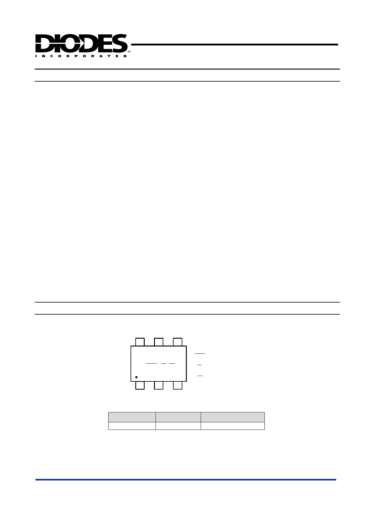
Marking Information
(1) SOT26
654
XX Y M
123
XX : Identification code
Y : Year: 0-9
M : Month: A~L
Part Number
AP1603W
Package
SOT26
Identification Code
EY
AP1603 Rev. 1
7 of 8
www.diodes.com
NOVEMBER 2006
© Diodes Incorporated
Share Link: 