AP1184(2014) データシートの表示(PDF) - Diodes Incorporated.
部品番号
コンポーネント説明
一致するリスト
AP1184
(Rev.:2014)
(Rev.:2014)
Diodes Incorporated.

AP1184 Datasheet PDF : 12 Pages
| |||
NOT RECOMMENDED FOR NEW DESIGN
AP1184
4A ULTRA LOW DROPOUT POSITIVE ADJUSTABLE OR
FIXED-MODE REGULATOR
Functional Descriptions (Continued)
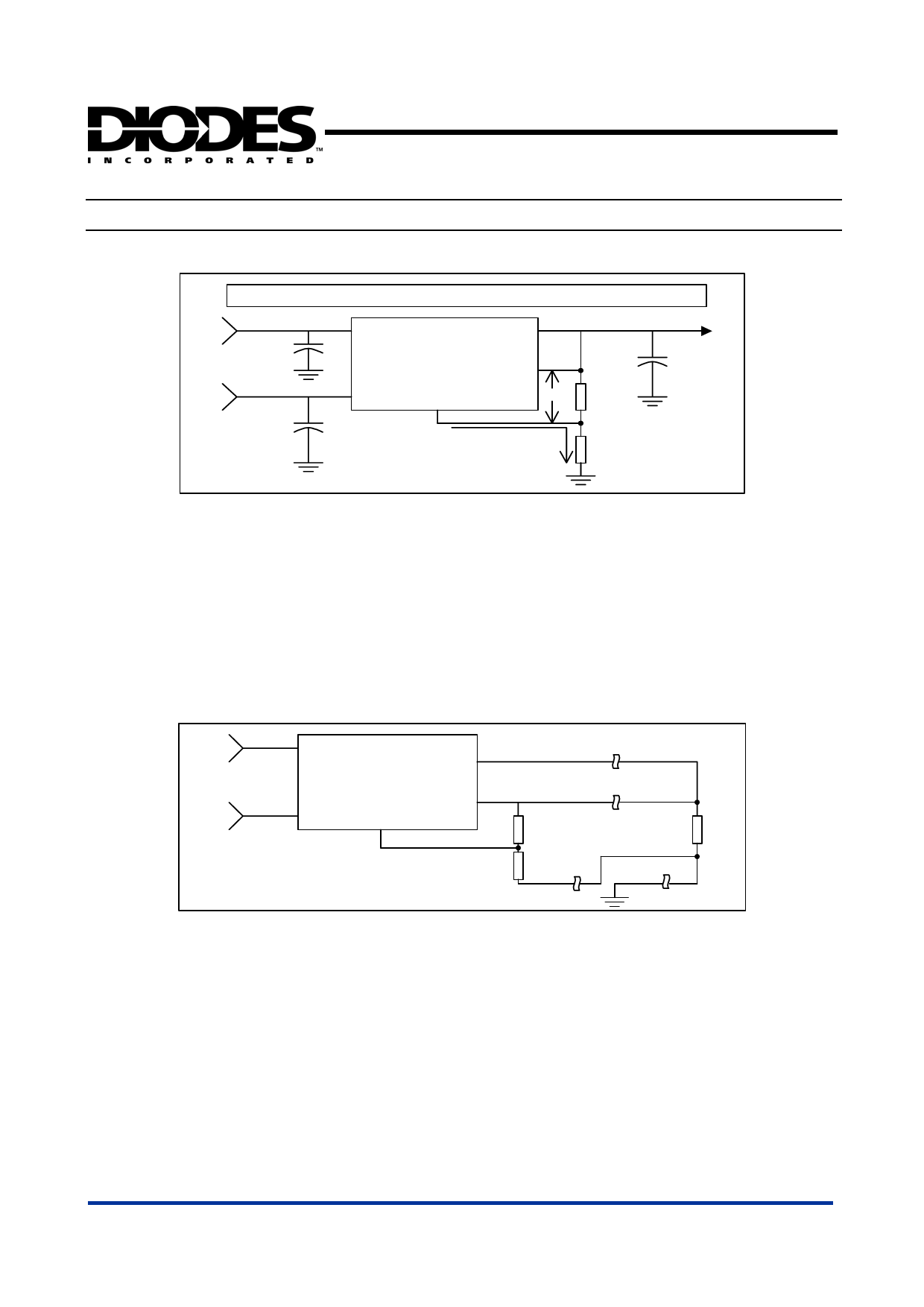
Vout = Vref (1+R2/R1) + Iadj * R2 where : Vref = 1.25V & Iadj=50uA Typically
Vin
Vctrl
AP1184-ADJ
Vsense
Adj
Vref R1+
Iadj=50uA
R2+
Vout
The AP1184-ADJ keeps a constant 1.25V between the Vsense pin and the Adj pin. By placing a resistor R1 across these two pins and
connecting the Vsense and Vout pin together, a constant current flows through R1, adding to the Iadj current and into the R2 resistor
producing a voltage equal to the (1.25/R1)*R2 + Iadj*R2. This voltage is then added to the 1.25V to set the output voltage. This is
summarized in the above equation. Since the minimum load current requirement of the AP1184-ADJ is 10mA, R1 is typically selected to
be a 121Ω resistor so that it automatically satisfies this condition. Notice that since the Iadj is typically in the range of 50uA it only adds a
small error to the output voltage and should be considered when very precise output voltage setting is required.
Load Regulation
Since the AP1184 has separate pins for the output (Vout) and the sense (Vsense), it is ideal for providing true remote sensing of the
output voltage at the load. This means that the voltage drops due to parasitic resistance such as PCB traces between the regulator and
the load are compensated for using remote sensing. Figure following shows a typical application of the AP1184-ADJ with remote sensing.
Vin
Vin
Vout
AP1184-ADJ
Vsense
Vctrl
Vctrl
Adj
R1
RL
R2
Stability
The AP1184-XXX requires the use of an output capacitor as part of the frequency compensation in order to make the regulator stable.
Typical designs for the microprocessor applications use standard electrolytic capacitors with typical ESR in the range of 50 to 100mΩ
and an output capacitance of 100uF to 1000uF. Fortunately as the capacitance increases, the ESR decreases resulting in a fixed RC
time constant. The AP1184-XXX takes advantage of the phenomena in making the overall regulator loop stable. For most applications a
minimum of 100uF aluminum electrolytic capacitor insures both stability and good transient response.
Thermal Design
The AP1184-XXX incorporates an internal thermal shutdown that protects the device when the junction temperature exceeds the
allowable maximum junction temperature. Although this device can operate with junction temperatures in the range of 150oC, it is
recommended that the selected heat sink be chosen such that during maximum continuous load operation, the junction temperature is
kept below this number. The example below shows the steps in selecting the proper surface mount package.
AP1184 Rev. 6 - 3
6 of 12
www.diodes.com
OCTOBER 2014
© Diodes Incorporated
Share Link: