AQW210HLAX データシートの表示(PDF) - Panasonic Corporation
部品番号
コンポーネント説明
一致するリスト
AQW210HLAX Datasheet PDF : 4 Pages
| |||
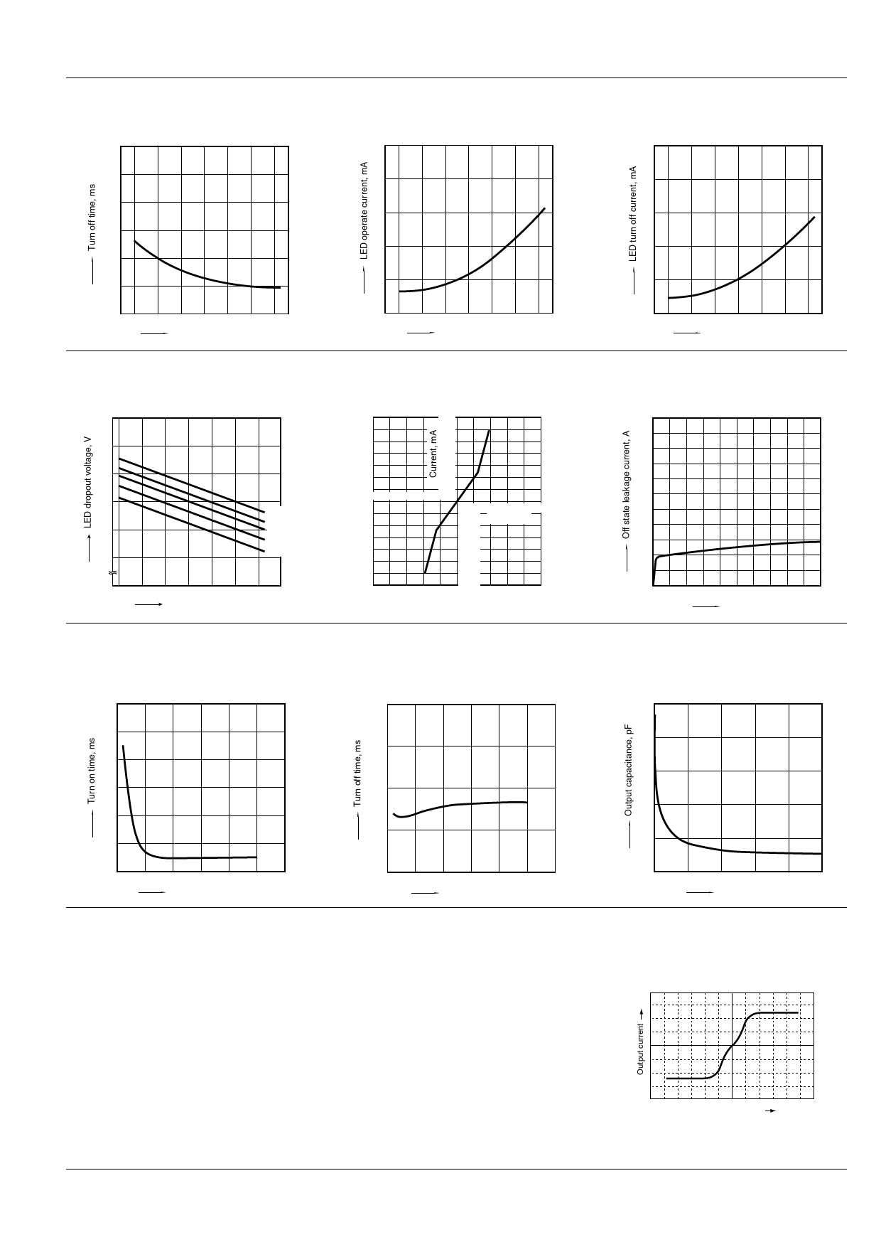
4. Turn off time vs. ambient temperature
characteristics
LED current: 5 mA; Load voltage: Max.(DC);
Continuous load current: Max.(DC)
0.3
0.25
0.2
0.15
0.1
0.05
0
–40 –20 0 20 40 60 80 85
Ambient temperature, °C
7. LED dropout voltage vs. ambient
temperature characteristics
LED current: 5 to 50 mA
1.5
1.4
1.3
1.2
50mA
30mA
1.1
20mA
10mA
5mA
1.0
0 –40 –20
0 20 40 60 80 85
Ambient temperature, °C
10. Turn on time vs. LED forward current
characteristics
Measured portion: between terminals 5 and 6, 7 and 8;
Load voltage: Max.(DC); Continuous load current:
Max.(DC); Ambient temperature: 25°C 77°F
3
2.5
2
1.5
1
0.5
0
10 20 30 40 50 60
LED forward current, mA
What is current limit
When a load current reaches the
specified output control current, a current
limit function works against the load
current to keep the current a constant
value.
The current limit circuit built into the
PhotoMOS thus controls the
instantaneous load current to effectively
ensure circuit safety.
GU 2 Form A Current Limiting (AQW210HL)
5. LED operate current vs. ambient
temperature characteristics
Load voltage: Max.(DC);
Continuous load current: Max.(DC)
5
6. LED turn off current vs. ambient temperature
characteristics
Load voltage: Max.(DC);
Continuous load current: Max.(DC)
5
4
4
3
3
2
2
1
1
0
–40 –20 0 20 40 60 80 85
Ambient temperature, °C
8. Current vs. voltage characteristics of output
at MOS portion
Measured portion: between terminals 5 and 6, 7 and 8;
Ambient temperature: 25°C 77°F
140
120
100
80
60
40
20
–5 –4 –3 –2 –1
1
–20
–40
2345
Voltage, V
–60
–80
–100
–120
–140
11. Turn off time vs. LED forward current
characteristics
Measured portion: between terminals 5 and 6, 7 and 8;
Load voltage: Max.(DC); Continuous load current:
Max.(DC); Ambient temperature: 25°C 77°F
0.2
0
–40 –20 0 20 40 60 80 85
Ambient temperature, °C
9. Off state leakage current vs. load voltage
characteristics
Measured portion: between terminals 5 and 6, 7 and 8;
Ambient temperature: 25°C 77°F
10 –3
10 –6
10 –9
10 –12
0
20
40
60
80 100
Load voltage, V
12. Output capacitance vs. applied voltage
characteristics
Measured portion: between terminals 5 and 6, 7 and 8;
Frequency: 1 MHz; Ambient temperature: 25°C 77°F
50
40
0.15
30
0.1
20
0.05
10
0
0 10 20 30 40 50 60
LED forward current, mA
0
0
10
20
30
40
50
Applied voltage, V
This safety feature protects circuits
downstream of the PhotoMOS against
over-current.
But, if the current-limiting feature is used
longer than the specified time, the
PhotoMOS can be destroyed. Therefore,
set the output loss to the max. rate or
less.
• Comparison of output voltage and
output current characteristics
V-I Characteristics
Output voltage
ASCTB56E 201201-T
Panasonic Corporation Automation Controls Business Unit industrial.panasonic.com/ac/e
Share Link: 