FAN2001 データシートの表示(PDF) - Fairchild Semiconductor
部品番号
コンポーネント説明
一致するリスト
FAN2001 Datasheet PDF : 11 Pages
| |||
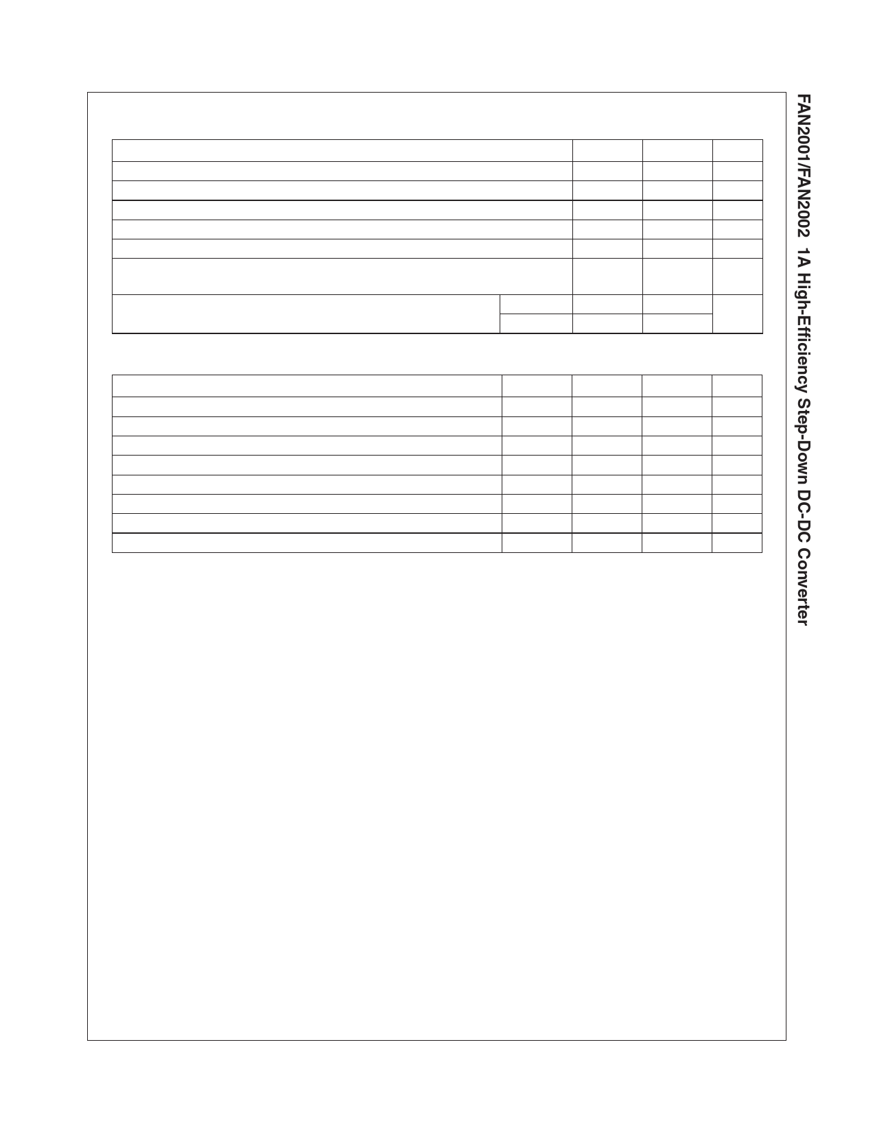
Absolute Maximum Ratings (Note1)
Parameter
VIN, PVIN
Voltage On Any Other Pin
Lead Soldering Temperature (10 seconds)
Junction Temperature
Storage Temperature
Thermal Resistance-Junction to Tab (θJC), 3x3mm 6-lead MLP (Note 2)
Electrostatic Discharge Protection (ESD) Level (Note 3)
Recommended Operating Conditions
Parameter
Supply Voltage Range
Output Voltage Range, Adjustable Version
Output Current
Inductor (Note 4)
Input Capacitor (Note 4)
Output Capacitor (Note 4)
Operating Ambient Temperature Range
Operating Junction Temperature Range
HBM
CDM
Min
-0.3
-0.3
-65
4
1
Max
7
V IN
260
150
150
8
Unit
V
V
°C
°C
°C
°C/W
kV
Min
2.5
0.8
-40
-40
Typ
3.3
10
2 x 10
Max
5.5
V IN
1
+85
+125
Unit
V
V
A
µH
µF
µF
°C
°C
Notes:
1. Stresses above those listed under “Absolute Maximum Ratings” may cause permanent damage to the device. This is a stress rating only and functional
operation of the device at these or any other conditions above those indicated in the operational section of this specification is not implied. Exposure
to absolute maximum rating conditions for extended periods may affect device reliability. Absolute maximum ratings apply individually only, not in
combination. Unless otherwise specified, all other voltages are referenced to AGND.
2. Junction to ambient thermal resistance, θJA, is a strong function of PCB material, board thickness, thickness and number of copper planes, number of
via used, diameter of via used, available copper surface, and attached heat sink characteristics.
3. Using Mil Std. 883E, method 3015.7(Human Body Model) and EIA/JESD22C101-A (Charge Device Model).
4. Refer to the applications section for further details.
FAN2001/FAN2002 Rev. 1.0.2
3
www.fairchildsemi.com
Share Link: 