ML6672 データシートの表示(PDF) - Micro Linear Corporation
部品番号
コンポーネント説明
一致するリスト
ML6672 Datasheet PDF : 8 Pages
| |||
FUNCTIONAL DESCRIPTION
The ML6672 transceiver is a physical media dependent
transceiver that allows the transmission and reception of
155 Mbps data over shielded twisted pair cable or
category 5 unshielded twisted pair cable.
The transmit section accepts NRZ data, sending the
information on a two pin current driven transmitter. The
transmitted output passes through an external low pass
filter and transformer before entering the connectors to the
STP or UTP cable. The output amplitude of the transmitted
signal is programmable through the external RTSET resistor.
The receive section accepts NRZ coded data after it
passes through an isolation transformer and band limiting
filter. The adaptive equalizer is used to compensate for the
amplitude and phase distortion incurred from the cable. The
adaptive control section determines the cable length and
adjusts the equalizer accordingly. As the input signal
amplitude diminishes, the amount of equalization increases
until it reaches its maximum of an equivalent 100 meters of
category 5 cable. A parallel 10pF capacitor can be connected
between TPIN+ and TPIN– to improve Bit Error Rate.
The adaptive control block governs both the equalization
level as well as the link detection status. The link detection
threshold has a fixed relationship to the overall
equalization level which is currently 25% of the
transmitted amplitude. For the link status to be true, a
minimum level signal must be received. When the input
signal is small, the equalization will be at its maximum.
After the signal has been equalized, it is fed through the
loopback multiplexer onto the RXOUT± pins.
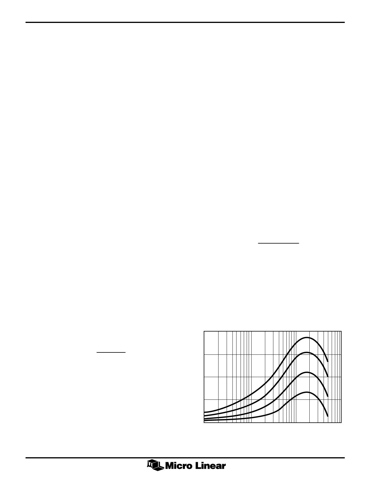
Figure 1 shows a typical gain vs frequency plot of the
adaptive equalizer for 0, 25, 50, 75 and 100 meter
category 5 cable lengths.
TRANSMISSION
PECL level scrambled NRZ data is received by the
ML6672 and the current driven transmitter then sent the
data to the filter/transformer module. The transmit
amplitude is controlled by one external resistor, RTSET.
IOUT
=
64 ´ 1.25V
RTSET
For ATM UTP applications the transmit amplitude is 1V
peak to peak. The termination at the transmitter output is
50W. Therefore the transmit current IOUT = 1/50 = 20 mA.
Therefore, RTSET = (64 x 1.25/20)kW = 4kW
The transmitter may be disabled via the TXOFF pin. When
this pin is pulled low, the transmitter’s output goes to its
center value (IOUT/2) with no differential current flowing
through the transformer.
ML6672
ADAPTIVE EQUALIZATION
During transmission of data over UTP (unshielded twisted
pair), distortion and ISI are caused by dispersion in the
cable. Equalization is used to overcome this signal
corruption. However, the distortion is frequency
dependent and loop length dependent. Therefore, in most
practical cases, the TP port characteristic is unknown and
it is impractical to tune the equalizer specifically to each
individual port. Hence, adaptive equalizer is used in the
TP-PMD to ensue proper compensation of the received
signal.
By using adaptive equalizer, the receiver automatically
compensate different length of cable without over
equalizing or under equalizing the line. The ML6672
monitors the energy of the received signal to determine
the cable length and adjust the equalizer accordingly. The
input signal level is inversely proportional to the cable
length. Therefore, as the signal level decreases, the
amount of equalization is increased to compensate for the
line loss.
RECEIVE CIRCUIT
After the data is received and equalized, it is then sent to
the clock recovery circuit via the RXOUT pins. A resistor
RTH is used to control the internal level of equalization.
VAMP
=
16 ´ 1.25 ´ RTH
RSET
VAMP is the transmit voltage amplitude and is equal to 1V
and RSET = 5kW. Therefore, RTH = 1 x 5/(16 x 1.25) kW =
250W.
CAP1 and CAP2 are capacitors used to set the time
constant for adaptation of the equalizer loop and should
be 0.33µF.
20
15
10
5
0 1 x 10⁶
1 x 10⁷
1 x 10⁸
Figure 1. Equalization Range
1 x 10⁹
5
Share Link: 