LB11961(2016) データシートの表示(PDF) - ON Semiconductor
部品番号
コンポーネント説明
一致するリスト
LB11961 Datasheet PDF : 8 Pages
| |||
Application Circuit Example
LB11961
*2
CM
HB
*7
H
IN
VCC
*3
IN
6VREG
*6
FG
*5
RD
RMI
*8
OUT1
CP = 100pF
*4
CT = 0.47F to 1F
VTH
CPWM
CT
S-GND
OUT2
F-GND
*1
F-GND
*1. Power supply and ground lines
P-GND is connected to the motor power supply system and S-GND is connected to the control circuit power supply
system.
These two systems should be formed from separate lines and the control system external components should be
connected to S-GND.
*2. Regeneration power supply stabilization capacitor
The capacitor CM provides power supply stabilization for both PWM drive and kickback absorption. A capacitor with a
value of over 0.1µF is used for CM. A large capacitor must be used when the coil inductance is large or when the coil
resistance is low. Since this IC adopts a technique in which switching is performed by the high side transistor and
regeneration is handled by the low side transistor, the pattern connecting CM to VM and P-GND must be as wide and as
short as possible.
*3. Hall sensor input
Lines that are as short as possible must be used to prevent noise from entering the system. The Hall sensor input circuit
consists of a comparator with hysteresis (20mV). We recommend that the Hall sensor input level be at least three times
this hysteresis, i.e. at least 60mVp-p.
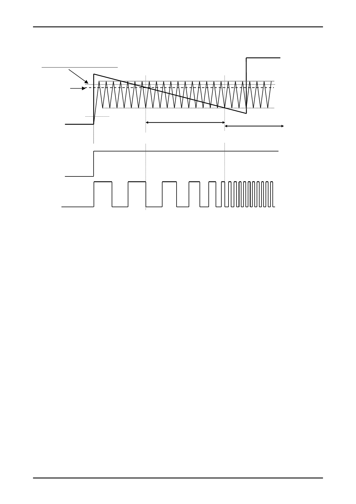
*4. PWM oscillator frequency setting capacitor
If a value of 100pF is used for CP, the oscillator frequency will be f = 25kHz, and this will be the basic frequency of the
PWM signal.
*5. RD output
This is an open collector output. It outputs a low level when the motor is turning and a high level when it is stopped. This
pin must be left open if unused.
www.onsemi.com
6
Share Link: 