AMS2905 データシートの表示(PDF) - Advanced Monolithic Systems Inc
部品番号
コンポーネント説明
一致するリスト
AMS2905 Datasheet PDF : 8 Pages
| |||
AMS2905
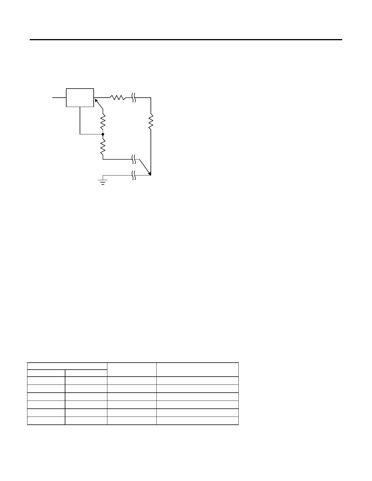
APPLICATION HINTS
Connected as shown , RP is not multiplied by the divider ratio
RP
PARASITIC
AMS2905
LINE RESISTANCE
VIN
IN OUT
ADJ
R1*
RL
R2*
*CONNECT R1 TO CASE
CONNECT R2 TO LOAD
Figure 3. Connections for Best Load Regulation
In the case of fixed voltage devices the top of R1 is connected
Kelvin internally, and the ground pin can be used for negative
side sensing.
The total thermal resistance from junction to ambient can be as
low as 45°C/W. This requires a reasonable sized PC board with
at least on layer of copper to spread the heat across the board and
couple it into the surrounding air.
Experiments have shown that the heat spreading copper layer
does not need to be electrically connected to the tab of the device.
The PC material can be very effective at transmitting heat
between the pad area, attached to the pad of the device, and a
ground plane layer either inside or on the opposite side of the
board. Although the actual thermal resistance of the PC material
is high, the Length/Area ratio of the thermal resistance between
layers is small. The data in Table 1, was taken using 1/16” FR-4
board with 1 oz. copper foil, and it can be used as a rough
guideline for estimating thermal resistance.
For each application the thermal resistance will be affected by
thermal interactions with other components on the board. To
determine the actual value some experimentation will be
necessary.
The power dissipation of the AMS2905 is equal to:
PD = ( VIN - VOUT )( IOUT )
Maximum junction temperature will be equal to:
TJ = TA(MAX) + PD(Thermal Resistance (junction-to-ambient))
Maximum junction temperature must not exceed 125°C.
Ripple Rejection
Thermal Considerations
The AMS2905 series have internal power and thermal limiting
circuitry designed to protect the device under overload conditions.
However maximum junction temperature ratings of 125°C should
not be exceeded under continuous normal load conditions.
Careful consideration must be given to all sources of thermal
resistance from junction to ambient. For the surface mount
package SOT-223 additional heat sources mounted near the
device must be considered. The heat dissipation capability of the
PC board and its copper traces is used as a heat sink for the
device. The thermal resistance from the junction to the tab for the
AMS2905 is 15°C/W. Thermal resistance from tab to ambient
can be as low as 30°C/W.
The ripple rejection values are measured with the adjustment pin
bypassed. The impedance of the adjust pin capacitor at the ripple
frequency should be less than the value of R1 (normally 100Ω to
200Ω) for a proper bypassing and ripple rejection approaching
the values shown. The size of the required adjust pin capacitor is
a function of the input ripple frequency. If R1=100Ω at 120Hz
the adjust pin capacitor should be >13µF. At 10kHz only 0.16µF
is needed.
The ripple rejection will be a function of output voltage, in
circuits without an adjust pin bypass capacitor. The output ripple
will increase directly as a ratio of the output voltage to the
reference voltage (VOUT / VREF).
Table 1.
COPPER AREA
TOP SIDE* BACK SIDE BOARD AREA
2500 Sq. mm 2500 Sq. mm
2500 Sq. mm
1000 Sq. mm 2500 Sq. mm
2500 Sq. mm
225 Sq. mm 2500 Sq. mm
2500 Sq. mm
100 Sq. mm 2500 Sq. mm
2500 Sq. mm
1000 Sq. mm 1000 Sq. mm
1000 Sq. mm
1000 Sq. mm
0
1000 Sq. mm
* Tab of device attached to topside copper.
THERMAL RESISTANCE
(JUNCTION-TO-AMBIENT)
45°C/W
45°C/W
53°C/W
59°C/W
52°C/W
55°C/W
Advanced Monolithic Systems, Inc. 6680B Sierra Lane, Dublin, CA 94568 Phone (925) 556-9090 Fax (925) 556-9140
Share Link: 