PBL38573 データシートの表示(PDF) - Ericsson
部品番号
コンポーネント説明
一致するリスト
PBL38573 Datasheet PDF : 15 Pages
| |||
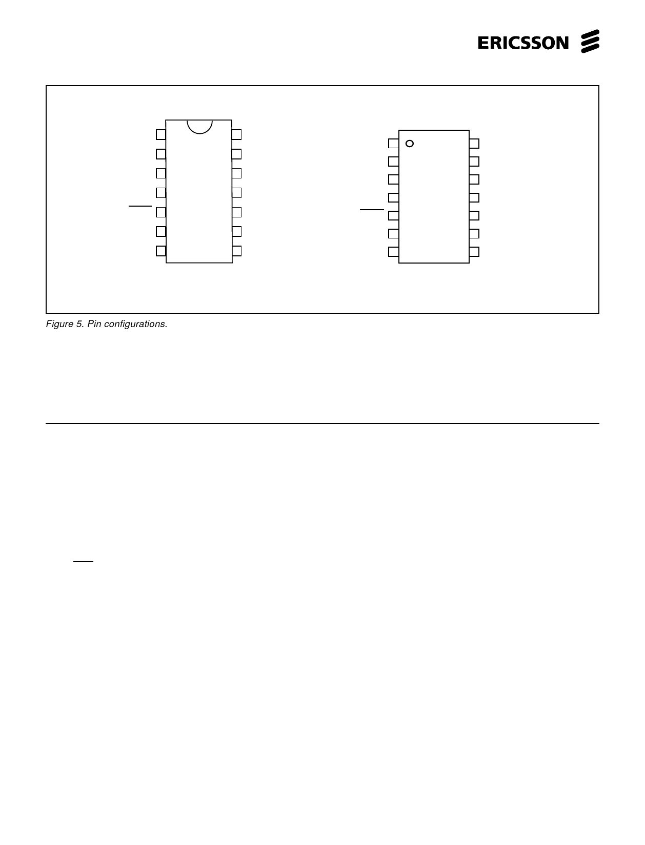
PBL 385 73
+L 1
TO 2
TI 3
+C 4
Mute 5
GR 6
DCO 7
14 RE 2
13 RE 1
12 RI
11 -L
10 MI 2
9 MI 1
8 MO
14-pin DIP
Figure 5. Pin configurations.
+L 1
TO 2
TI 3
+C 4
Mute 5
GR 6
DCO 7
14 RE 2
13 RE 1
12 RI
117 -L
106 MI 2
9 MI 1
8 MO
14-pin SO
Pin Descriptions:
Refer to figure 5.
Pin Name
Function
1 +L
2 TO
3 TI
4 +C
5 Mute
6 GR
7 DCO
8 MO
} 9 MI 1
10 MI 2
11 -L
12 RI
} 13 RE 1
14 RE 2
Output of the DC-regulator and transmit amplifier. This pin is connected to the line through a polarity
guard diode bridge.
Output of the transmit amplifier. This pin is connected through a resistor of 47 to 100 ohm to -L,
sets the DC-resistance of the circuit. The output has a low AC output impedance and the
signal is used to drive a side tone balancing network.
Input of transmit amplifier. Input impedance 17 kohm ± 20 %.
Positive power supply terminal for most of the circuitry inside the PBL 385 73 ( current consumption
about 1 mA). The +C pin shall be connected to a decoupling capacitor of 47 µF to 150 µF.
Maximum voltage (to mute) is 0.3 V, current sink requirement of external driver is 100 µA.
Input of the gain regulation with line length.
Output of the auxiliary DC-supply.
Output of the microphone amplifier or DTMF-amplifier.
Microphone amplifier Inputs. Input impedance 1.7 kohm ± 20 %.
The negative power terminal, connected to the line through a polarity guard diode bridge.
Input of receiver amplifier. Input impedance 38 kohm ± 20 %.
Receiver amplifier outputs. Output impedance is approximately 3 ohm.
4
Share Link: 