CA-MLF32A-A-Z-T-01 データシートの表示(PDF) - Unspecified
部品番号
コンポーネント説明
一致するリスト
CA-MLF32A-A-Z-T-01 Datasheet PDF : 2 Pages
| |||
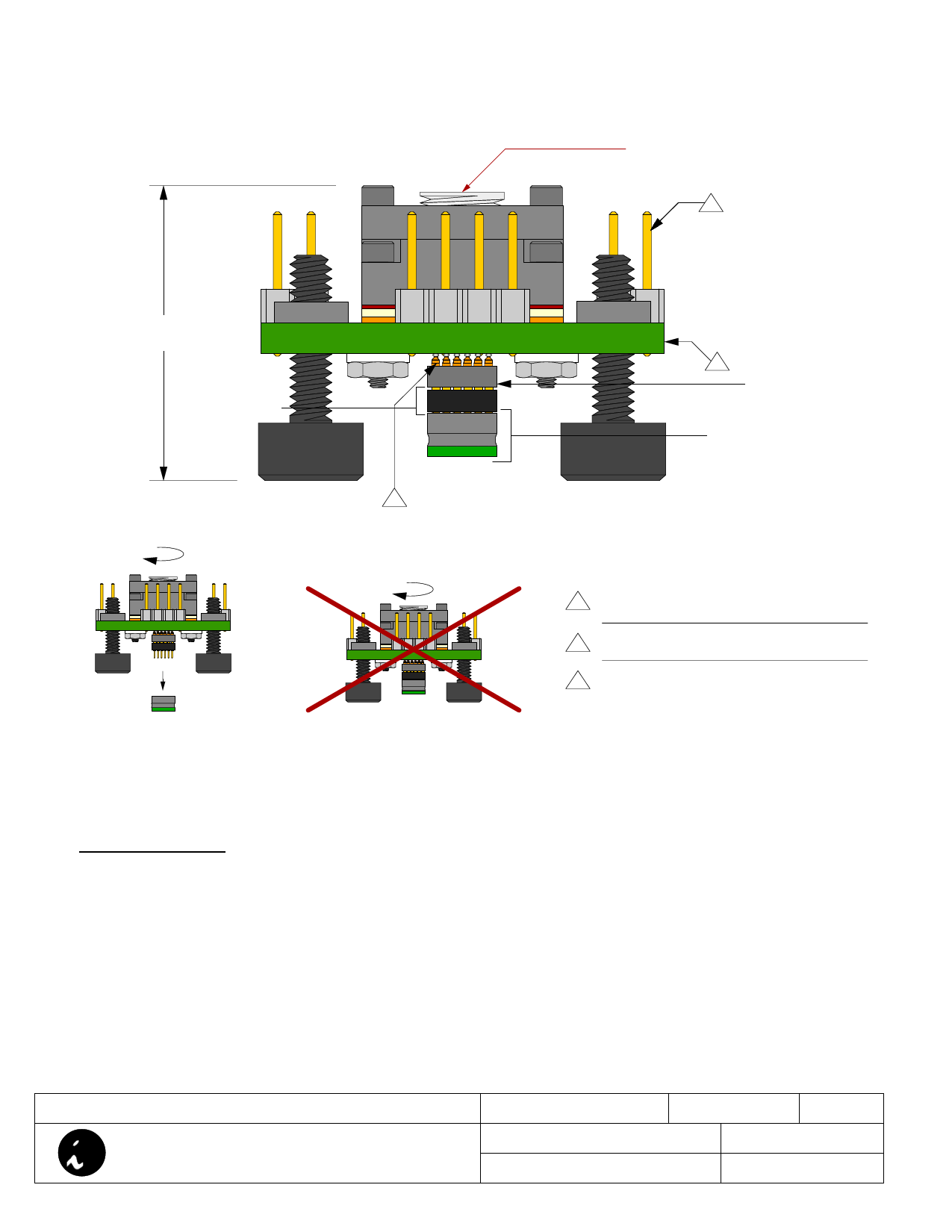
Recommended torque = 1.5 in. lbs.
(24 in. oz.)
3
22.31mm
[0.878"]
SK-UGA6/33A-03
2
1
2
Apply torque and then
plug into SF-MLF foot.
NOTE: Do not apply
torque when assemby is
pluged into SF-MLF foot.
1
board UGA
SF-MLF32A-A-02
Substrate: 2.34mm ±0.18mm [0.092" ±0.007"]
1 FR4/G10 or equivalent high temp material. 17µm
[1/2 oz.] Cu clad. SnPb plating.
2
Pins: material- Brass Alloy 360 1/2 hard; finish-
0.25µm [10µ"] Au over 1.27µm [50µ"] Ni (min.).
Test points: material- Phosphor Bronze; plating-
3 Sn over 1.27µm [50µ"] Ni. Gold flash on contact
end.
User Instructions:
1. Attach SF-MLF32A-A-02 foot to the target board.
2. Turn plastic thumb screws until head touches bottom of CA-MLF32A-A-Z-T-01 board.
3. Insert SK-UGA6/33A-03 into board UGA. Check orientation.
4. Remove socket lid and compression plate.
5. Insert MLF package into IC guide inside socket cavity.
6.Put compression plate and socket lid in place.
7. Hold socket assembly and apply recommended torque.
8. Carefully insert CA-MLF assembly into SF-MLF feet UGA. Check orientation.
9. Unscrew plastic thumb screws until they hit target board.
CA-MLF32A-A-Z-T-01 Drawing
© 2004 IRONWOOD ELECTRONICS, INC.
PO BOX 21151 ST. PAUL, MN 55121
Tele: (651) 452-8100
www.ironwoodelectronics.com
Status: Released
Scale: 3:1
Rev: B
Drawing: H. Hansen
Date: 4/5/04
File: CA-MLF32A-A-Z-T-01 Dwg
Modified: 6/26/05
Share Link: 