82559ER データシートの表示(PDF) - Intel
部品番号
コンポーネント説明
一致するリスト
82559ER Datasheet PDF : 94 Pages
| |||
GD82559ER — Networking Silicon
3.2.2
Interface Control Signals
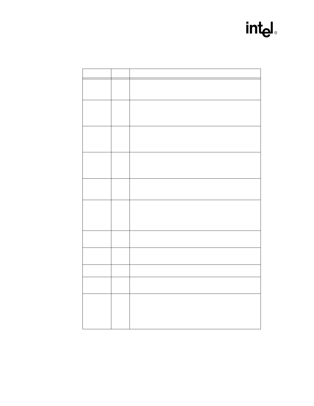
Symbol
FRAME#
IRDY#
TRDY#
STOP#
IDSEL
DEVSEL#
REQ#
GNT#
INTA#
SERR#
PERR#
Type
S/T/S
S/T/S
S/T/S
S/T/S
IN
S/T/S
T/S
IN
O/D
O/D
S/T/S
Name and Function
Cycle Frame. The cycle frame signal is driven by the current master
to indicate the beginning and duration of a transaction. FRAME# is
asserted to indicate the start of a transaction and de-asserted during
the final data phase.
Initiator Ready. The initiator ready signal indicates the bus master’s
ability to complete the current data phase and is used in conjunction
with the target ready (TRDY#) signal. A data phase is completed on
any clock cycle where both IRDY# and TRDY# are sampled asserted
(low) simultaneously.
Target Ready. The target ready signal indicates the selected device’s
ability to complete the current data phase and is used in conjunction
with the initiator ready (IRDY#) signal. A data phase is completed on
any clock cycle where both IRDY# and TRDY# are sampled asserted
(low) simultaneously.
Stop. The stop signal is driven by the target to indicate to the initiator
that it wishes to stop the current transaction. As a bus slave, STOP# is
driven by the 82559ER to inform the bus master to stop the current
transaction. As a bus master, STOP# is received by the 82559ER to
stop the current transaction.
Initialization Device Select. The initialization device select signal is
used by the 82559ER as a chip select during PCI configuration read
and write transactions. This signal is provided by the host in PCI
systems.
Device Select. The device select signal is asserted by the target once
it has detected its address. As a bus master, the DEVSEL# is an input
signal to the 82559ER indicating whether any device on the bus has
been selected. As a bus slave, the 82559ER asserts DEVSEL# to
indicate that it has decoded its address as the target of the current
transaction.
Request. The request signal indicates to the bus arbiter that the
82559ER desires use of the bus. This is a point-to-point signal and
every bus master has its own REQ#.
Grant. The grant signal is asserted by the bus arbiter and indicates to
the 82559ER that access to the bus has been granted. This is a point-
to-point signal and every master has its own GNT#.
Interrupt A. The interrupt A signal is used to request an interrupt by
the 82559ER. This is an active low, level triggered interrupt signal.
System Error. The system error signal is used to report address
parity errors. When an error is detected, SERR# is driven low for a
single PCI clock.
Parity Error. The parity error signal is used to report data parity errors
during all PCI transactions except a Special Cycle. The parity error pin
is asserted two clock cycles after the error was detected by the device
receiving data. The minimum duration of PERR# is one clock for each
data phase where an error is detected. A device cannot report a parity
error until it has claimed the access by asserting DEVSEL# and
completed a data phase.
8
Datasheet
Share Link: 