XC9103 データシートの表示(PDF) - TOREX SEMICONDUCTOR
部品番号
コンポーネント説明
一致するリスト
XC9103 Datasheet PDF : 19 Pages
| |||
XC9103/04/05 Series
Ceramic Cap. Compatible Step-Up DC/DC Converters
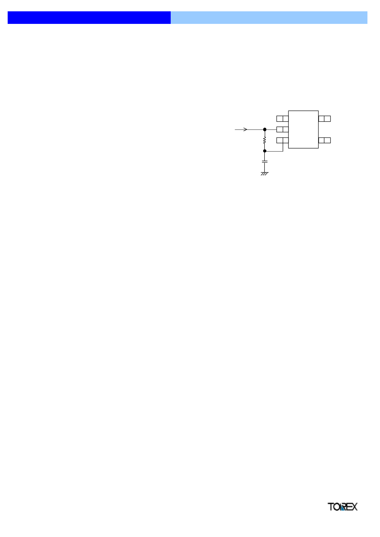
" NOTE ON HOW TO USE B TYPE
When applying voltage to VDD through CE pin with the series' B type product, the
limiter circuit may operate when a power supply is on, and the operation may not
start. In this case, as the right circuit indicates, please connect a resistor and a
capacitor with the CE pin. By the time constant, the CE pin will be chip enable after
VDD rise so that IC will be in the stable condition.
Please set time constant equal to 10ms by the following equation.
Time constant : τ (s) = R (Ω) x C (F)
[ Example of Equation ]
R = 100kΩ, C = 0.1µF
τ (s) = R (Ω) x C (F)
= 100kΩ x 0.1µF = 10ms
VDD
R
C
FB
CE/PWM
EXT
GND
" OPERATIONAL DESCRIPTION
The XC9103/04/05 series are step-up DC/DC converter controller ICs with built-in high speed, low ON resistance drivers.
<Error Amp.>
Error Amplifier is designed to monitor the output voltage, comparing the feedback voltage (FB) with the reference voltage Vref. In response to feedback
of a voltage lower than the reference voltage Vref, the output voltage of the error amp. decreases.
<OSC Generator>
This circuit generates the internal reference clock.
<Ramp Wave Generator>
The Ramp Wave Generator generates a saw-tooth waveform based on outputs from the OSC Generator.
<PWM Comparator>
The PWM comparator compares outputs from the Error Amp. and saw-tooth waveform. When the voltage from the Error Amp's output is low, the
external switch will be set to ON.
<PWM/PFM Controller>
This circuit generates PFM pulses.
The PWM/PFM automatic switching mode switches between PWM and PFM automatically depending on the load. The PWM/PFM automatic switching
mode is selected when the voltage of the CE pin is less than VDD - 1.0V, and the control switches between PWM and PFM automatically depending on
the load. PWM/PFM control turns into PFM control when threshold voltage becomes lower than voltage of error amps. PWM control mode is selected
when the voltage of the CE pin is more than VDD - 0.2V. Noise is easily reduced with PWM control since the switching frequency is fixed. The series is
suitable for noise sensitive portable audio equipment as PWM control can suppress noise during operation and PWM/PFM switching control can reduce
consumption current during light load in stand-by.
<Vref 1 with Soft Start>
The reference voltage, Vref (FB pin voltage)=0.9V, is adjusted and fixed by laser trimming (for output voltage settings, please refer to the notes on page
8). To protect against inrush current, when the power is switched on, and also to protect against voltage overshoot, soft-start time is set internally to
10ms. It should be noted, however, that this circuit does not protect the load capacitor (CL) from inrush current. With the Vref voltage limited and
depending upon the input to the error amps, the operation maintains a balance between the two inputs of the error amps and controls the EXT pin's ON
time so that it doesn't increase more than is necessary.
<Enable Function>
This function controls the operation and shutdown of the IC. When the voltage of the CE pin is 0.2V or less, the mode will be disable, the channel's
operations will stop and the EXT1 pin will be kept at a low level (the external N-type MOSFET will be OFF). When the IC is in a state of disable, current
consumption will be no more than 1.0µA.
When the CE pin's voltage is 0.65V or more, the mode will be enable and operations will recommence.
Semiconductor Ltd.
7
Share Link: 