ST662ACD-TR(2007) データシートの表示(PDF) - STMicroelectronics
部品番号
コンポーネント説明
一致するリスト
ST662ACD-TR
(Rev.:2007)
(Rev.:2007)
STMicroelectronics

ST662ACD-TR Datasheet PDF : 20 Pages
| |||
Pin configuration
2
Pin configuration
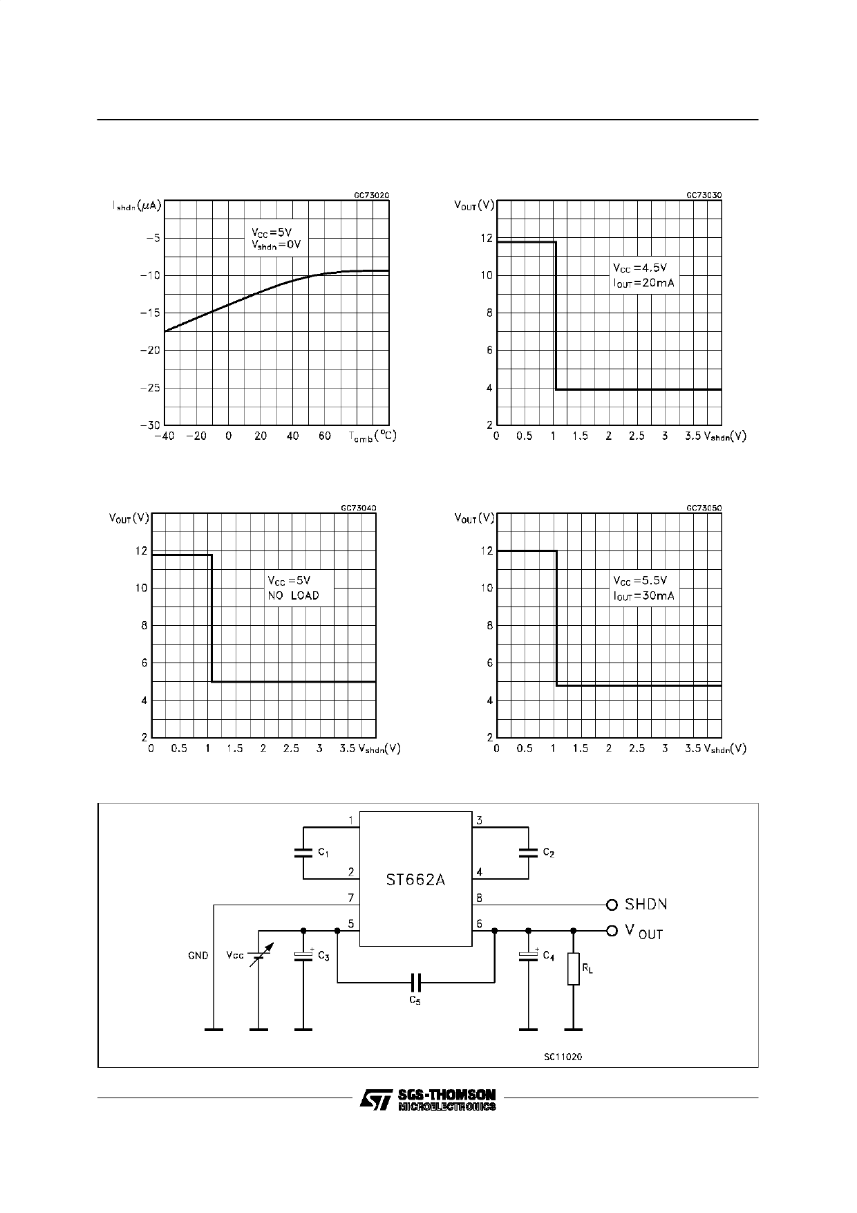
Figure 2. Pin connections (top view)
ST662AB - ST662AC
Table 2.
Pin N°
1
2
3
4
5
6
7
8
Pin description
Symbol
Name and function
C1-
Negative terminal for the first charge pump capacitor
C1+
C2-
C2+
VCC
VOUT
GND
SHDN
Positive terminal for the first charge pump capacitor
Negative terminal for the second charge pump capacitor
Positive terminal for the second charge pump capacitor
Supply voltage
12V output voltage VOUT = VCC when in shutdown mode
Ground
Active high C-MOS logic level shutdown input. SHDN is internally pulled up to VCC.
Connect to GND for normal operation. In Shutdown mode the charge pumps are turned
off and VOUT = VCC
4/20
Share Link: