TDA1575T データシートの表示(PDF) - Philips Electronics
部品番号
コンポーネント説明
一致するリスト
TDA1575T Datasheet PDF : 16 Pages
| |||
Philips Semiconductors
FM front end circuit for
CENELEC EN 55020 applications
Preliminary specification
TDA1575T
SYMBOL
PARAMETER
CONDITIONS
Linear IF amplifier
IF = 10.7 MHz
V11,12
Z12-11
C12-11
V10
Z10
C10
VO
Gv
∆Gv
NF
DC input voltage (pins 11 and 12)
input impedance
input capacitance
DC output voltage (pin 10)
output impedance
output capacitance
output signal (RMS value)
IF voltage gain (20 log (V10−4 / V12−11))
IF voltage gain deviation
noise figure
−1 dB compression
Tamb= −40 to +85 °C
RS = 300 Ω
Note
1. GP = 10 log (4Vo mix ×10.7 MHz) / (EMF2 × 98 MHz)2 × (RS1 / RML).
MIN.
−
240
−
−
240
−
−
27
−
−
TYP.
1.25
300
13
4.4
300
3
−
30
0
6.5
MAX.
−
360
−
−
360
−
650
−
−
−
UNIT
V
Ω
pF
V
Ω
pF
mV
dB
dB
dB
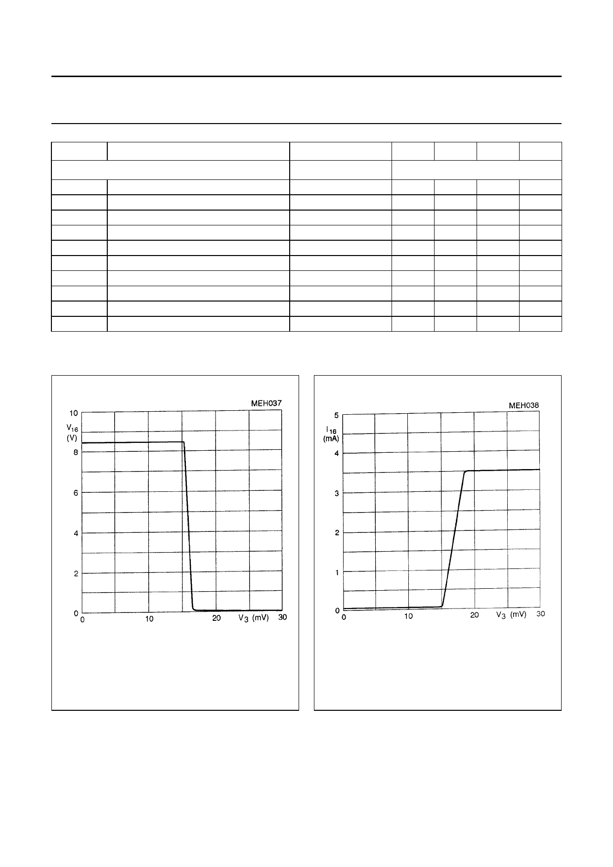
Fig.3 AGC output voltage V16 as a function of
Vi3 RMS at I16 = 0, measured in test circuit
Fig.1.
Fig.4 AGC output current I16 as a function of
Vi3 RMS at V16 = 8.5 V, measured in test
circuit Fig.1.
April 1993
6
Share Link: 