TC74LCX74FT データシートの表示(PDF) - Toshiba
部品番号
コンポーネント説明
一致するリスト
TC74LCX74FT Datasheet PDF : 10 Pages
| |||
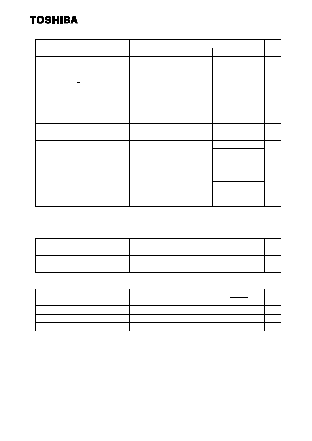
AC Characteristics (Ta = −40 to 85°C)
TC74LCX74F/FN/FT/FK
Characteristics
Symbol
Test Condition
Maximum clock frequency
Propagation delay time
(CK-Q, Q )
Propagation delay time
( CLR , PR -Q, Q )
Minimum pulse width
(CK)
Minimum pulse width
( CLR , PR )
Minimum setup time
fmax Figure 1, Figure 2
tpLH
Figure 1, Figure 2
tpHL
tpLH
Figure 1, Figure 4
tpHL
tW (H)
Figure 1, Figure 2, Figure 3
tW (L)
tW (L) Figure 1, Figure 2, Figure 3
ts Figure 1, Figure 2
Minimum hold time
th Figure 1, Figure 2
Minimum removal time
trem Figure 1, Figure 3
Output to output skew
tosLH
tosHL
Note: Parameter guaranteed by design.
(tosLH = |tpLHm − tpLHn|, tosHL = |tpHLm − tpHLn|)
Min Max Unit
VCC (V)
2.7
⎯
⎯
MHz
3.3 ± 0.3 150 ⎯
2.7
⎯
8.0
ns
3.3 ± 0.3 1.5 7.0
2.7
⎯
8.0
ns
3.3 ± 0.3 1.5 7.0
2.7
3.3
⎯
ns
3.3 ± 0.3 3.3
⎯
2.7
3.6
⎯
ns
3.3 ± 0.3 3.3
⎯
2.7
2.5
⎯
ns
3.3 ± 0.3 2.5
⎯
2.7
1.5
⎯
ns
3.3 ± 0.3 1.5
⎯
2.7
3.0
⎯
ns
3.3 ± 0.3 2.5
⎯
2.7
⎯
⎯
(Note)
ns
3.3 ± 0.3 ⎯
1.0
Dynamic Switching Characteristics (Ta = 25°C, input: tr = tf = 2.5 ns, CL = 50 pF, RL = 500 Ω)
Characteristics
Symbol
Test Condition
Quiet output maximum dynamic VOL
Quiet output minimum dynamic VOL
VOLP VIH = 3.3 V, VIL = 0 V
|VOLV| VIH = 3.3 V, VIL = 0 V
Typ. Unit
VCC (V)
3.3
0.8
V
3.3
0.8
V
Capacitive Characteristics (Ta = 25°C)
Characteristics
Input capacitance
Output capacitance
Power dissipation capacitance
Symbol
CIN
COUT
CPD
fIN = 10 MHz
Test Condition
⎯
⎯
Typ. Unit
VCC (V)
3.3
7
pF
0
8
pF
(Note) 3.3
25
pF
Note:
CPD is defined as the value of the internal equivalent capacitance which is calculated from the operating
current consumption without load.
Average operating current can be obtained by the equation:
ICC (opr) = CPD・VCC・fIN + ICC/2 (per bit)
4
2007-10-19
Share Link: 