TDA1572 データシートの表示(PDF) - Philips Electronics
部品番号
コンポーネント説明
一致するリスト
TDA1572 Datasheet PDF : 19 Pages
| |||
Philips Semiconductors
AM receiver circuit
Product specification
TDA1572
PARAMETER
Unwanted signals
Suppression of IF whistles at
Vi = 15 µV; m = 0% related to AF signal
of m = 30%
at fi ≈ 2 × fIF
at fi ≈ 3 × fIF
IF suppression at RF input;
for symmetrical input
for asymmetrical input
Residual oscillator signal at mixer output;
at fosc
at 2 × fosc
SYMBOL
MIN.
TYP. MAX. UNIT
α2IF
α3IF
αIF
αIF
I1(osc)
I1(2osc)
−
**
−
dB
−
**
−
dB
−
40
−
dB
−
40
−
dB
−
1
−
µA
−
1,1
−
µA
* AF signals at the IF output will be suppressed by a coupling capacitor to the demodulator and by full wave-detection in
the demodulator.
** Value to be fixed.
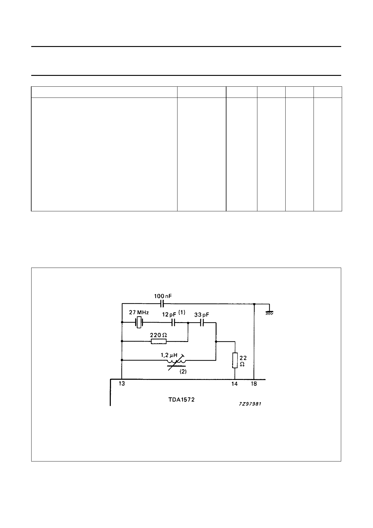
APPLICATION INFORMATION
(1) Capacitor values depend on crystal type.
(2) Coil data: 9 windings of 0,1 mm dia laminated Cu wire on TOKO coil set 7K 199CN; Qo = 80.
Fig.2 Oscillator circuit using quartz crystal; centre frequency = 27 MHz.
December 1987
9
Share Link: 