BCC200PS03 データシートの表示(PDF) - International Power DC Power Supplies
部品番号
コンポーネント説明
一致するリスト
BCC200PS03 Datasheet PDF : 2 Pages
| |||
Models and Ratings
Output
Power
165 W
200 W
210 W
240 W
264 W
400 W
405 W
408 W
405 W
396 W
408 W
406 W
Output
Voltage
3.3 V
5.0 V
7.5 V
12.0 V
3.3 V
5.0 V
7.5 V
12.0 V
15.0 V
18.0 V
24.0 V
28.0 V
Notes
1. For -40 ºC operating temperature, add suffix ‘-L’ to model number.
2. For conformally coated option, add suffix ‘-E’ to model number.
3. 600 W model available for OEM quantities - contact sales.
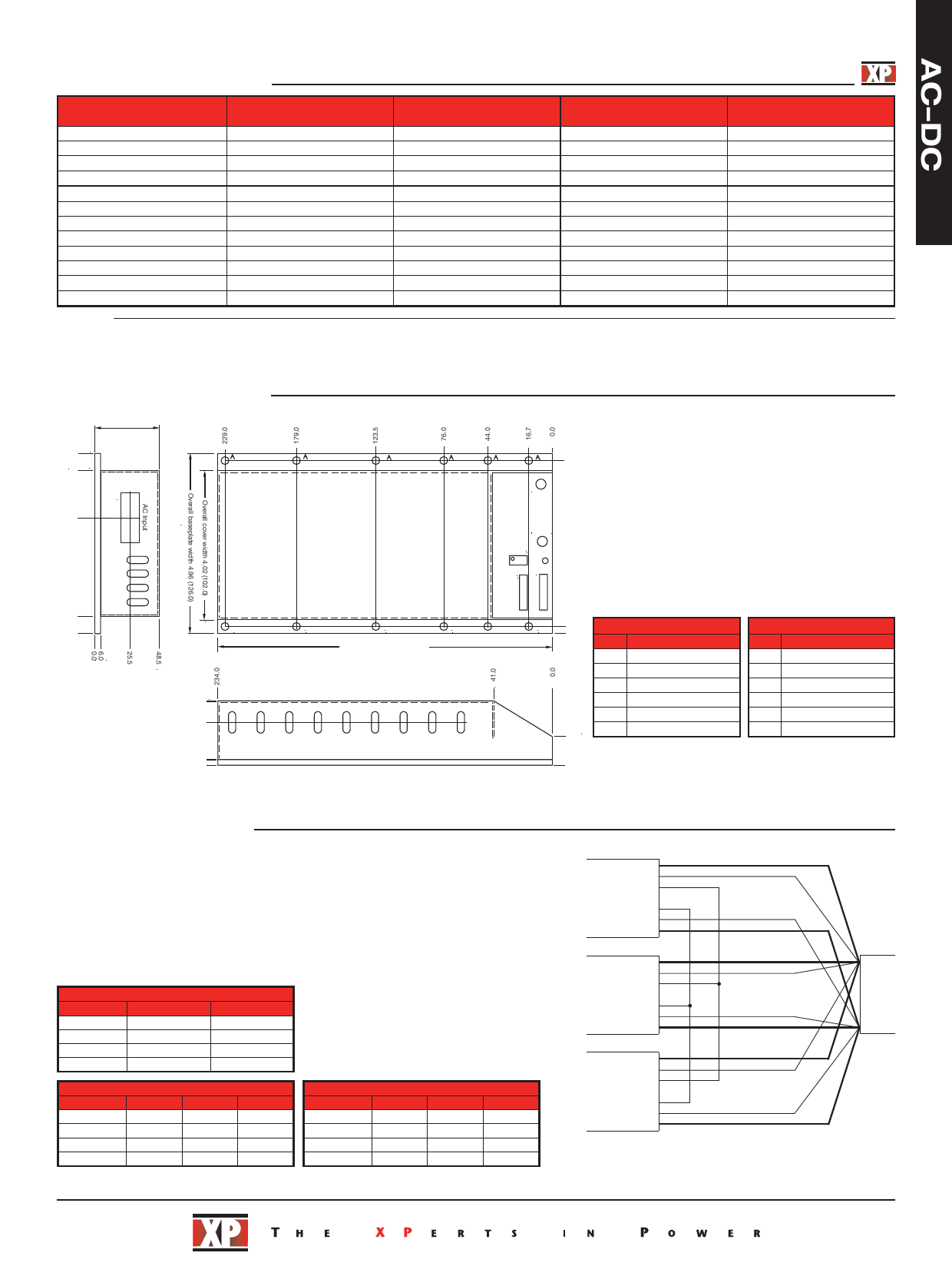
Mechanical Details
127.0
114.5
Overall height
1.90 (48.5)
A = 0.18 ” (4.5 mm) mounting holes for M4
50.0
Centers
55.5
Centers
47.5
Centers
3
81.5
1
TOP VIEW
12.5
0.0
A
A
A
Overall length 9.21 (234.0)
48.5
32.0
Output
Current
50.0 A
40.0 A
28.0 A
20.0 A
80.0 A
80.0 A
54.0 A
34.0 A
27.0 A
22.0 A
17.0 A
14.5 A
Output
Load Regulation
1.5%
1.5%
1.5%
1.5%
1.5%
1.5%
1.5%
1.0%
1.0%
1.0%
1.0%
1.0%
BCC
Model
Number(1,2)
BCC200PS03
BCC200PS05
BCC200PS07
BCC200PS12
BCC400PS03
BCC400PS05
BCC400PS07
BCC400PS12
BCC400PS15
BCC400PS18
BCC400PS24
BCC400PS28
32.0
Centers
A
27.3
Centers
–
Output
+
Output
Output Set DC OK
PL1 PL2
1
1
66
A
A
Input:
AMP Mate'n'lok 3 way.
Mating housing AMP 350766-1.
121.5
Socket crimp AMP 926893-1.
Pin 3: Live
Pin 2: Earth
Pin 1: Neutral
Output:
Power output +ve and -ve by M6 studs.
Use appropriate ring terminals and wire for the load current.
Maximum torque: 17.7 lbs-in (2 Nm)
Signal connections on two 0.1 (2.5) headers (PL1 & PL2).
Mating Housing: Molex 22-01-2065.
Mating Crimp: Molex 08-50-0032.
5.5
PL1 Connections
0.0
Pin
Function
1
Current Balance
2
Voltage Balance
3
Trim
4
-Remote Sense
5
+Remote Sense
6
22.0
Remote On/Off
PL2 Connections
Pin
Function
1
Current Balance
2
Voltage Balance
3
Trim
4
-Remote Sense
5
+Remote Sense
6
Remote On/Off
6.0
0.0
Overall dimensions are in inches (mm)
Weight: 2.87 lbs (1.3 kg)
0.0
Tolerance: ±0.05 in (±1.5 mm) length and width
±0.02 in (±0.5 mm) height
Accessories
1. Input & output connector kit - order part ‘BCC CONKIT’.
2. For thermal pad, order part ‘BCC THERM’.
Application Notes
Current and voltage balance pins are used to connect units in parallel - see drawing.
Remote On/Off: Output is on with pin left floating, pull pin down to -Output to turn
output off.
Examples of parallel operation
+VOUT
+S
VB
Remote sense pins are used to compensate for lead drops, for up to 0.5 V maximum.
TRM
When not used, move switch SW1 to local positions. See below for switch positions.
CB
-S
The BCC series is approximately 80% efficient, so for 400 W load consumption,
-VOUT
the cooling system used will have to be able to absorb 100 W while maintaining the
baseplate to a maximum of +83 °C.
+VOUT
+
+S
Remote sense switchers - single unit
Remote
Local
SW1 D (1)
OFF
ON
SW1 C (2)
OFF
ON
SW1 B (3)
ON
OFF
SW1 A (4)
ON
OFF
VB
TRM
CB
-S
-VOUT
+VOUT
+S
Load
-
Parallel units with remote sense
PSU 1 PSU 2 PSU 3
SW1 D (1) OFF
OFF
OFF
SW1 C (2) OFF
OFF
OFF
SW1 B (3)
ON
OFF
OFF
SW1 A (4)
ON
OFF
OFF
Parallel units without remote sense
PSU 1 PSU 2 PSU 3
SW1 D (1)
ON
OFF
OFF
SW1 C (2)
ON
OFF
OFF
SW1 B (3) OFF
OFF
OFF
SW1 A (4) OFF
OFF
OFF
Contact sales office for a full set of application notes.
VB
TRM
CB
-S
-VOUT
Ensure output power leads are of equal length and type for all
units and that they are capable of carrying the load current. Set all
units to the required output ±0.1V. The voltage setting pot on unit
1 can be used to set the overall output voltage if required.
08-Jan-10
Share Link: 