SI4743 データシートの表示(PDF) - Silicon Laboratories
部品番号
コンポーネント説明
一致するリスト
SI4743 Datasheet PDF : 68 Pages
| |||
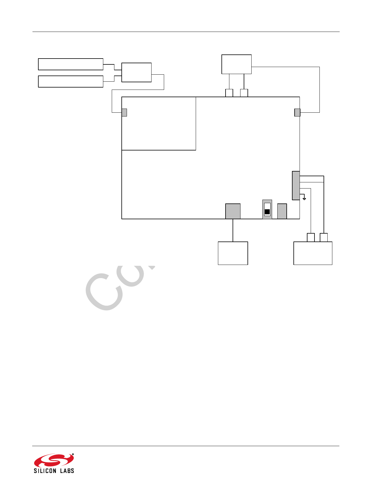
AN388
R&S SML01 Generator 1
R&S SML01 Generator 2
Power
Combiner
J2
Si474x
AM/FM Receiver
Daughter board
Audio
Analyzer
RXS
Digital Audio IN.
RCA Cable
J6
RCA OUT
Line
J30
SPDIF
OUT
Si47xx
Base board
USB
SW1
EXT pwr
J76
1
2
3
4
Power Connector
1. VMCU
2. VIO
3. VDD
4. GND
J79
USB pwr
USB Cable
PC
with USB
port
J78
EXT Jack
CH
CH
1
2
Agilent
E3646A
Power Supply
Figure 3. Si474x FM Tuner Setup
2.1. FM Tuner Testing Measurement Considerations
Several issues must be considered to make accurate measurements.
First, the power combiner and cable losses must be calibrated and factored into each measurement. The loss for
the Mini-Circuit power combiner is approximately 6 dB.
Second, most signal generators display the voltage generated at the input of the device under test (DUT) assuming
an input resistance of 50 . For example, if the signal generator displays VL = 1 µV (0 dBµV), the generator source
voltage VS is 2 µV (6 dBµV). The load voltage VL is generated from the source voltage VS by the voltage divider
created by the 50 generator source resistance RS and the 50 load resistance RL. This distinction is important
only for sensitivity, RDS sensitivity, and IP3, which are specified in µV electromotive force (EMF), where EMF
refers to the source voltage VS. Measurements such as AM suppression, selectivity, and spurious response are
relative and may be referenced using VS or VL. To summarize, the generator displays the voltage at the input of the
DUT. In the case of Si47xx FM tuner, input impedance is high; therefore, to convert the value displayed on the
signal generator to EMF, double the voltage (add 6 dB).
Rev. 0.2
9
Share Link: 