PD1394P11ABD データシートの表示(PDF) - Philips Electronics
部品番号
コンポーネント説明
一致するリスト
PD1394P11ABD Datasheet PDF : 20 Pages
| |||
Philips Semiconductors
3-port physical layer interface
Preliminary specification
PDI1394P11A
17.1 Arbitrated (short) Bus Reset
A 1394-1995 software initiated bus reset assumes that the state of
the bus is unknown when reset occurs and requires that the reset be
long enough to permit the longest transaction to finish and still
complete reset (167µs min. to 250µs max.). The total duration of bus
initialization is longer than the nominal isochronous cycle time
(125µs) and may disrupt two isochronous periods. This compels
device designers to add additional buffer depth to preserve the
smooth flow of isochronous data from the perspective of their
application. If a node that initiates a reset arbitrates for control of the
bus prior to asserting reset, arbitration time can be shortened
significantly (1.3µs min. to 80µs max.). This 1394a concept is known
as Arbitrated (short) Bus Reset, and is incorporated in the
PDI1394P11A.
The TESTM2 (pin 21) pins is used to enable Arbitrated (short) Bus
Reset mode. In 1394-1995 mode, this pin is tied high. In this mode,
an arbitrated bus reset cannot be initiated from this node and will be
treated as a “long” bus reset if initiated by another node. In
accordance with the 1394-1995 spec, all bus resets on the entire
bus will be “long”.
To enable Arbitrated (short) Bus Reset mode, set TESTM2 low.
With the part in this mode, writing a 1 to the ISBR (Initiate Short Bus
Reset) bit (bit 7) of Phy register 9 initiates an arbitrated bus reset.
This mode also allows the Phy to recognize arbitrated bus resets
initiated by other nodes. Non-arbitrated bus resets can still be
initiated from this node and are recognized and processed correctly
when initiated by another node.
17.2 Setting the CPS Trip Point
The Cable Power Status (CPS) pin (pin 23) is used to monitor the
cable power. When cable power voltage has dropped too low for
reliable operation, internal circuitry trips, which clears the CPS bits
in the Phy registers (bit 7 of register 0, and bit 2 of register 6). This
action causes a cable power status interrupt which sets the CPSint
bit in the Phy registers (bit 1 of register 6). This bit can be cleared by
a hardware reset or by writing a 0 to the CPSint bit. However, if the
CPS input is still low, another cable-power status interrupt
immediately occurs. The cable voltage at which these events occur
is adjustable on the PDI1394P11A.
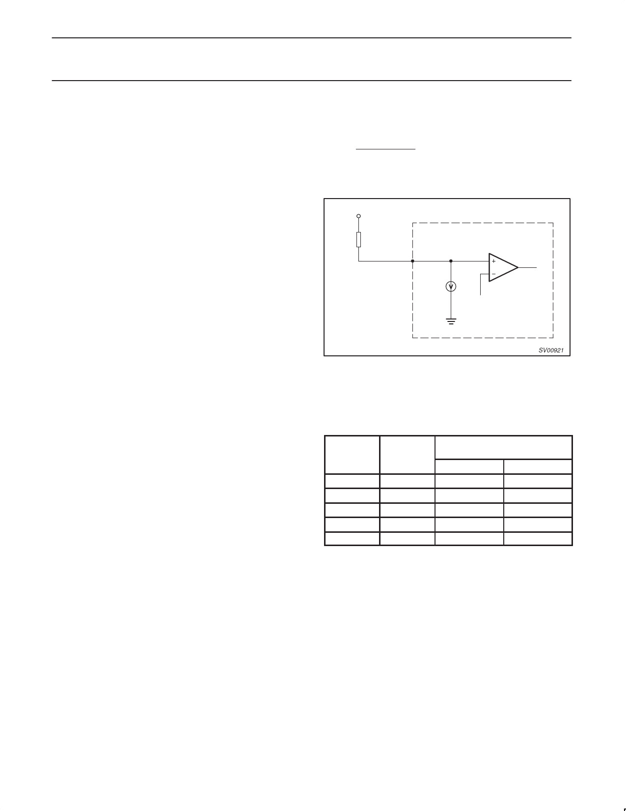
The external resistor (R) needed to set the CPS trip voltage (Vcable)
to a desired voltage can be calculated using the following equation:
R
+
(Vcable * 1.85V)
10mA
The external and internal circuitry associated with the CPS pin is
illustrated in Figure 5.
Vcable
R
CPS
COMPARATOR
Icomp
10µA
Vcomp
1.85V
Figure 5.
Phy
SV00921
Some typical threshold voltage values and their associated resistor
values are shown in Table 1.
Table 1. Typical threshold voltage values
Vcable (V)
R (kΩ)
Vcable DETECTOR
TOLERANCE % WITH:
R of 5%
R of 2%
5
315
6.8
4.4
6
415
7.3
4.8
7
515
7.8
5.2
8
615
8.3
5.6
9
715
8.8
6.0
1999 Mar 10
11
Share Link: 