PCF8573 データシートの表示(PDF) - Philips Electronics
部品番号
コンポーネント説明
一致するリスト
PCF8573 Datasheet PDF : 28 Pages
| |||
Philips Semiconductors
Clock/calendar with serial I/O
Product specification
PCF8573
handbook, halfpage
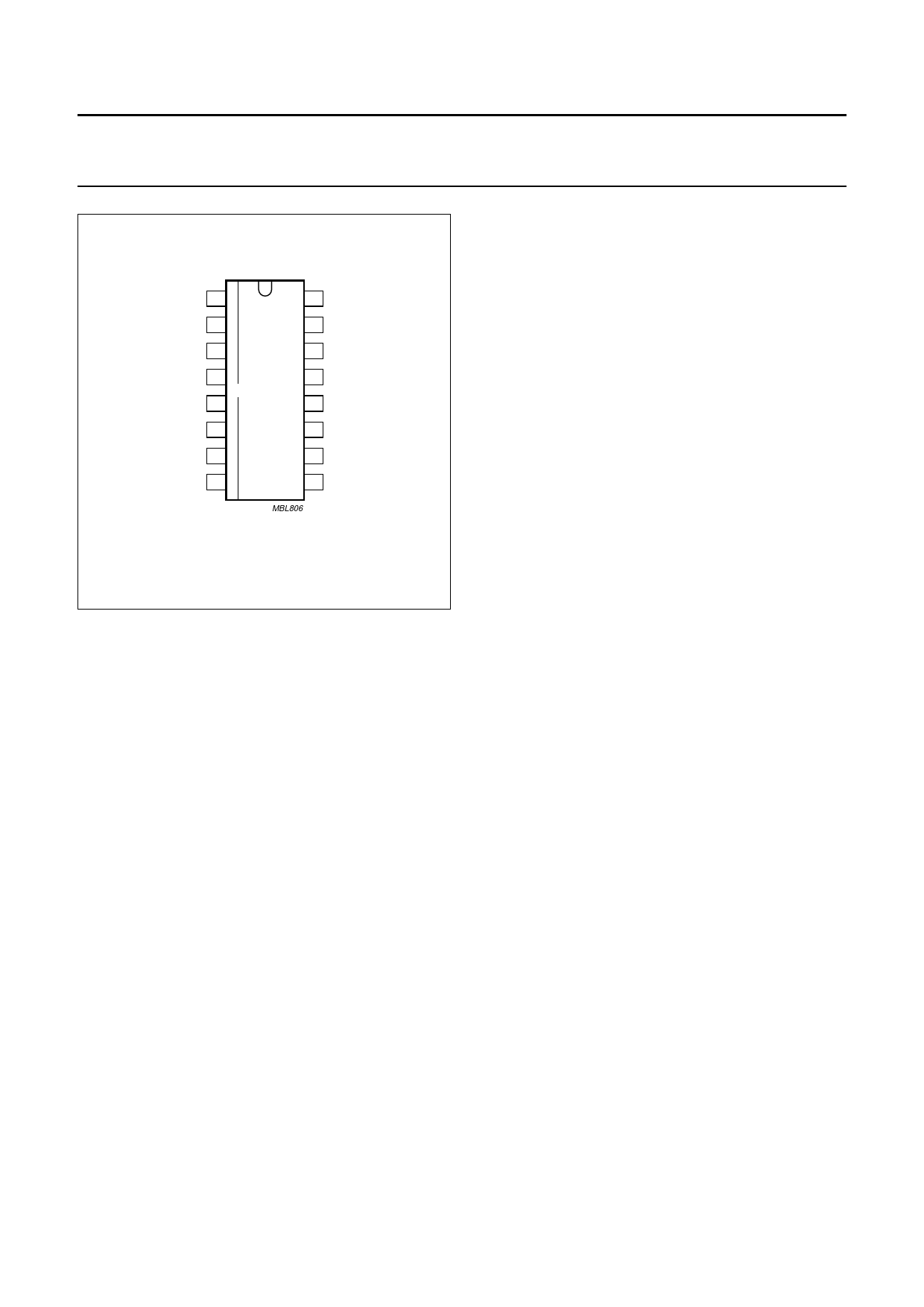
A0 1
A1 2
COMP 3
16 VDD
15 VSS1
14 OSCO
SDA 4
13 OSCI
PCF8573T
SCL 5
12 TEST
EXTPF 6
11 FSET
PFIN 7
10 SEC
VSS2 8
9 MIN
MBL806
Fig.3 Pinning diagram (SO16).
7 FUNCTIONAL DESCRIPTION
7.1 Oscillator
The PCF8573 has an integrated crystal-controlled
oscillator which provides the timebase for the prescaler.
The frequency is determined by a single 32.768 kHz
crystal connected between OSCI and OSCO. A trimmer is
connected between OSCI and VDD.
7.2 Prescaler and time counter
The prescaler provides a 128 Hz signal at the FSET output
for fine adjustment of the crystal oscillator without loading
it. The prescaler also generates a pulse once a second to
advance the seconds counter. The carry of the prescaler
and the seconds counter are available at the outputs SEC,
MIN respectively, and are also readable via the I2C-bus.
The mark-to-space ratio of both signals is 1 : 1. The time
counter is advanced one count by the falling edge of output
signal MIN. A transition from HIGH-to-LOW of output
signal SEC triggers MIN to change state.
The time counter counts minutes, hours, days and months,
and provides a full calendar function which needs to be
corrected only once every four years - to allow for
leap-year. Cycle lengths are shown in Table 1.
7.3 Alarm register
The alarm register is a 24-bit memory. It stores the
time-point for the next setting of the status flag COMP.
Details of writing and reading of the alarm register are
included in the description of the characteristics of the
I2C-bus.
7.4 Comparator
The comparator compares the contents of the alarm
register and the time counter, each with a length of 24 bits.
When these contents are equal the flag COMP will be set
4 ms after the falling edge of MIN. This set condition
occurs once at the beginning of each minute. This
information is latched, but can be cleared by an instruction
via the I2C-bus. A clear instruction may be transmitted
immediately after the flag is set and will be executed. Flag
COMP information is also available at the output COMP.
The comparison may be based upon hours and minutes
only if the internal flag NODA (no date) is set. Flag NODA
can be set and cleared by separate instructions via the
I2C-bus, but it is undefined until the first set or clear
instruction has been received. Both COMP and NODA
flags are readable via the I2C-bus.
2003 Jan 27
5
Share Link: 