PBL38570 データシートの表示(PDF) - Ericsson
部品番号
コンポーネント説明
一致するリスト
PBL38570 Datasheet PDF : 12 Pages
| |||
PBL 385 70
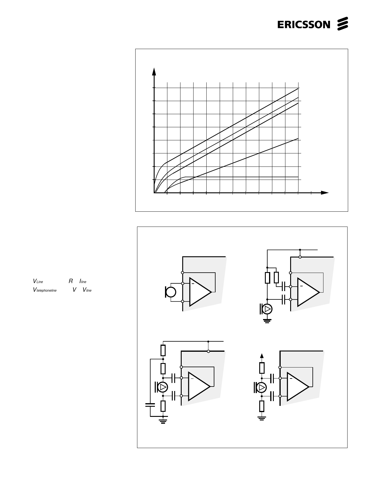
DC - characteristic
The DC - characteristic that a telephone
set has to fulfill is mainly given by the
network administrator.Following para-
meters are useful to know when the DC
behaviour of the telephone is to be set:
The voltage of the feeding system.
The line feeding resistance 2x... ohms.
The maximum current from the line at
zero line length.
The min. current at which the telephone
has to work (basic function).
The lowest and highest voltage
permissible across the telephone set.
The highest voltage that the telephone
may have at different line currents is
normally set by the network owners
specification. The lowest voltage for the
telephone is normally set by the voltages
that are needed for the different parts of
the telephone to function. For ex. for trans-
mitter output amplifier, receiver output
amplifier, dialler, speech switching and
loudspeaker amplifier in a handsfree
telephone etc.
R6 will set the slope of the DC-char. and
the rest of the level is set by some constants
in the circuit as shown in the equation
below. The slope of the DC-char. will also
influence the line length regulation (when
used ) and thus the gain of both transmitter
and receiver. See the table under gain
regulation.
VLine ≈ 2 + 1. 5 ⋅R 6 ⋅Iline
Vtelephoneline ≈ 1. 5V + Vline
Microphone amplifier
The microphone amplifier in PBL38570
is divided into two stages. The first stage is
a true differential amplifier providing high
CMRR (-55 to -65 dB typical) with voltage
gain of 19 dB. This stage is followed by a
gain regulated amplifier with a regulation
range of 5 ± 2 dB. The input of the
microphone amplifier can be used for
dynamic or electret transducers.
See fig. 8.
An electret microphone with a built in
FET amplifier is to be seen from outside as
a high impedance constant current gene-
rator and is normally specified with a load
resistance of ≈ 2k. This is to be considered
as max. value and by using it will render the
max. gain from the microphone. This level
of input signal that is unnecessary high will
result in clipping in the microphone amplifier
and could in mute condition permeate
through the input to the circuits reference
V
16
14
12
10
8
6
4
2
20
40
60
Figure 7. DC-characteristics. (R6 = 75Ω)
(a)
PBL 385 70
11
12
M
13 +
Dynamic
microphone
R
C+
(c)
11
4
PBL 385 70
12
M
13 +
Balanced electret microphone.
An additional RC filterlink is
recommended if pin 4 is used
as a supply.
Figure 8. Microphone options.
6
V telephone line
V line
V pin 4
V pin 2
V pin 8 o. 9
(DC supply)
IL
80
100
120
mA
(b)
4 PBL 385 70
11
12
M
13 +
Unbalanced electret
mic. with balanced
signal, DC-supply from
pin 4.
DC
Pin 8 or 9.
(d)
11
12
PBL 385 70
M
13 +
Balanced electret
microphone
Share Link: 