PI74FCT2861TR データシートの表示(PDF) - Pericom Semiconductor
部品番号
コンポーネント説明
一致するリスト
PI74FCT2861TR Datasheet PDF : 4 Pages
| |||
PI74FCT2861T
12345678901234567890123456789012123456789012345678901234567890121234567890123456789012345617089-0B12i1t2N345o6n78-9I0n12v3e45r6t7i8n90g12B34u56s78T90r1a21n23s4c5e67iv89e0r12
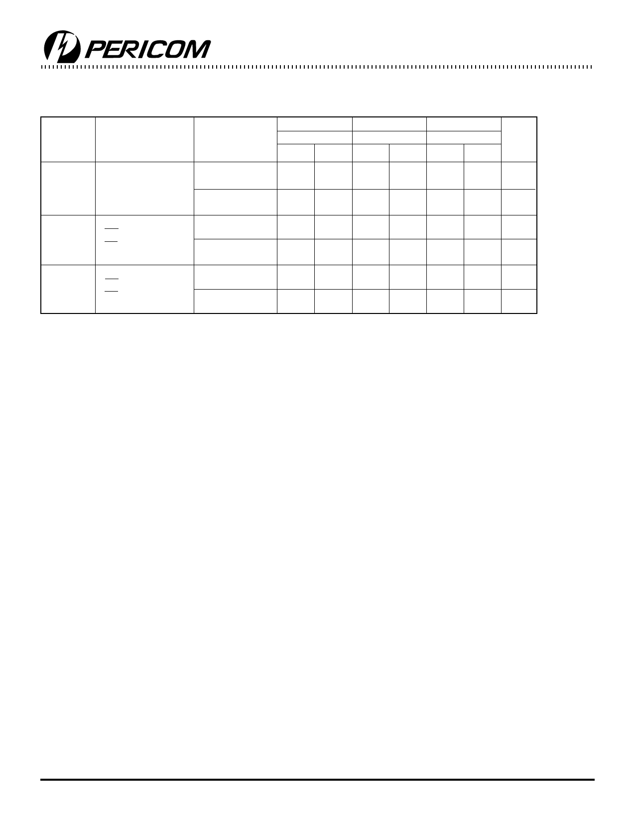
Non-inverting Switching Characteristics over Operating Range
Parameters Description
Conditions(1)
2861AT
2861BT
2861CT
Com.
Com.
Com.
Min. Max. Min. Max. Min. Max. Unit
tPLH
Propagation Delay
CL = 50pF
tPHL
RN to TN or
RL = 500Ω
TN to RN
CL = 300pF(3)
RL = 500Ω
tPZH
Output Enable Time
CL = 50pF
tPZL
OET to TN or
RL = 500Ω
OER to RN
CL = 300pF(3)
RL = 500Ω
tPHZ
Output Disable Time(3)
CL = 50pF
tPLZ
OET to TN or
RL = 500Ω
OER to RN
CL = 5pF(3)
RL = 500Ω
1.5
8.0
1.5
6.0
1.5
5.5
ns
1.5 17.0 1.5 13.0 1.5 11.5
ns
1.5 12.0 1.5
8.0
1.5
6.8
ns
1.5 20.0 1.5 15.0 1.5 13.0
ns
1.5
9.0
1.5
6.0
1.5
5.0
ns
1.5 10.0 1.5
7.0
1.5
6.0
ns
Notes:
1. See test circuit and wave forms.
2. Minimum limits are guaranteed but not tested on Propagation Delays.
3. This parameter is guaranteed but not production tested.
Pericom Semiconductor Corporation
2380 Bering Drive • San Jose, CA 95131 • 1-800-435-2336 • Fax (408) 435-1100 • http://www.pericom.com
4
PS8339 09/29/98
Share Link: 