MSM7603 データシートの表示(PDF) - Oki Electric Industry
部品番号
コンポーネント説明
一致するリスト
MSM7603 Datasheet PDF : 20 Pages
| |||
¡ Semiconductor
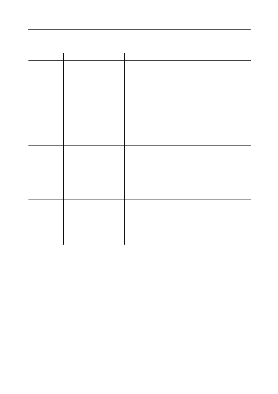
PIN DESCRIPTIONS
Pin
Symbol
1
NLP
2
HCL
3
ADP
4
SYNC
5
SCK
MSM7603/7603B
Type
I
I
I
I
I
Description
This is the control pin for the center clipping function to force
the SOUT output to a minimum value when the SOUT signal is
below –57 dBm0. Effective for reducing low-level noise.
"H": Center clip ON
"L": Center clip OFF
This is the through mode control pin.
When this pin is in the through mode the RIN and SIN data are
output to ROUT and SOUT. At the same time, the coefficient of
the adaptive FIR filter is cleared.
"H": Through mode
"L": Normal mode (echo canceler operates)
This is the AFF coefficient control pin which stops updating the
adaptive FIR filter (AFF) coefficient and sets it to a fixed value,
when the pin is configured to be the coefficient fix mode.
Used when holding the AFF coefficient which has been once
converged.
"H": Coefficient fix mode
"L": Normal mode (coefficient update)
This is the input pin for the sync signal for transmit/receive
serial data. This pin uses the external SYNC or SYNCO.
Inputs the PCM codec transmit/receive sync signal (8 kHz).
This is the clock input pin for transmit/receive serial data. It
uses the external SCK or the SCKO.
Input the PCM codec transmit/receive clock (64 to 2048 kHz).
4/20
Share Link: 