MM1501 データシートの表示(PDF) - Mitsumi
部品番号
コンポーネント説明
一致するリスト
MM1501 Datasheet PDF : 14 Pages
| |||
MITSUMI
Video Switch · 75Ω driver · Y/C mix MM1501
MM1511 ~ MM1512
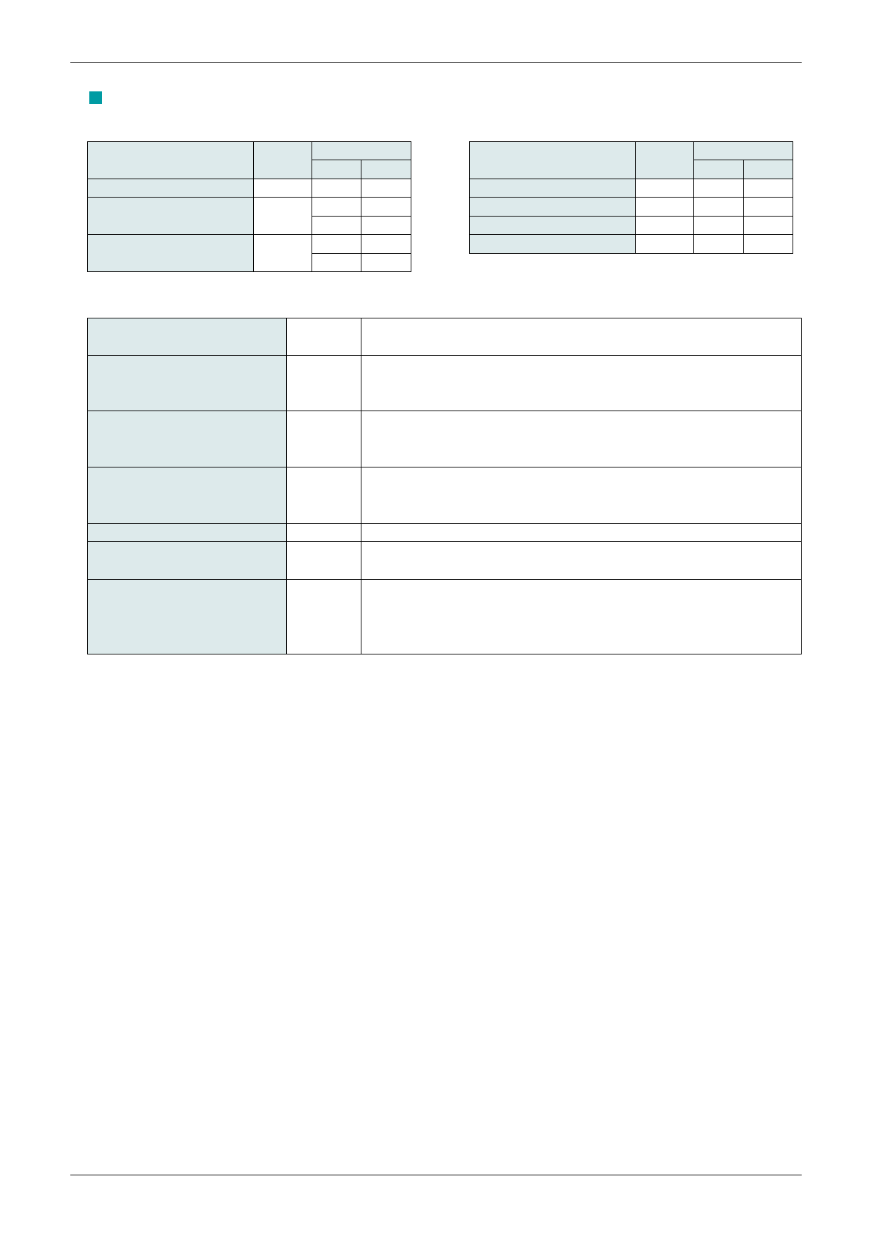
· Switch Status
Item
Consumption current
Voltage gain
Frequency characteristic
Symbol
ICC
GV
fc
Switch status
S1 S2
2
2
1
2
2
1
1
2
2
1
Item
Symbol
Switch status
S1 S2
Differential gain
DG
3
1
Differential phase
DP
3
1
Y output dynamic range VDY
2
1
C output dynamic range VDC
3
1
· Measurement Procedures
Consumption current
ICC1
Voltage gain
GV
Frequency characteristic
fc
Differential gain
DG
Differential phase
DP
Y output dynamic range
VDY
C output dynamic range
VDC
Connect a DC ammeter to the VCC pin and measure. Hereafter,
short the ammeter to use.
Input a 2.0VP-P (1.0VP-P for MM1512), 100kHz sine wave to SG1. If TP1
voltage is V1 and TP2 voltage is V2, find GV by the following formula:
GV = 20LOG (V2/V1) dB
In the above GV measurement, if TP2 voltage at 10MHz (7MHz for
MM1512) is V3, find fc by the following formula.
fc = 20LOG (V3/V2) dB
Input a 2.0VP-P (1.0VP-P for MM1512) to SG1, input a chroma signal
to SG2, and measure differential gain at TP2.
APL = 10 ~ 90%
The same as for DG, but measure differential phase.
Input a 100kHz sine wave to SG1. Measure VDY, the maximum
amplitude under THD 1%, at TP2.
Input an APL 50% luminance signal to SG1 and input a chroma
signal to SG2. Change the chroma signal amplitude and measure
VDC, the maximum amplitude where there is no waveform
distortion at TP2.
Share Link: 