MIC2590B(2002) データシートの表示(PDF) - Micrel
部品番号
コンポーネント説明
一致するリスト
MIC2590B Datasheet PDF : 24 Pages
| |||
MIC2590B
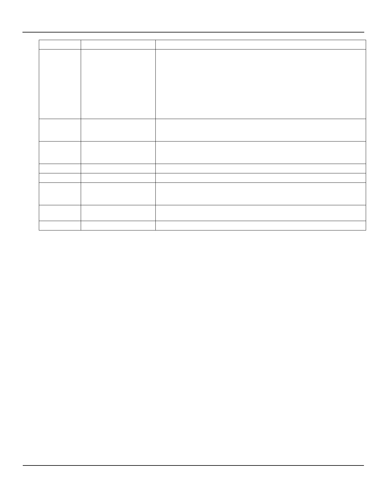
Pin Description
Pin Number
8, 29
14, 23
11, 26
15, 22
44, 43
1, 36
2, 35
37
Pin Name
5VGATEA, 5VGATEB
3VGATEA, 3VGATEB
VSTBY – 2 pins
VAUXA, VAUXB
ONA, ONB
/FAULTA, /FAULTB
CFILTERA, CFILTERB
/INT
Micrel
Pin Function
5V Gate Drive Outputs [A/B]: Each connects to the gate of an external N-
Channel MOSFET. During power-up the CGATE and the gate of the
MOSFETs are charged by a 20µA current source. This controls the value of
dv/dt seen at the source of the MOSFETs, and hence the current flowing into
the load capacitance.
During current limit events, the voltage at this pin is adjusted to maintain
constant current through the switch for a period of tFLT. Whenever an
overcurrent, thermal shutdown or input undervoltage fault condition occurs
the GATE pin for the affected slot is immediately brought low.
During power-down these pins are discharged by an internal current source.
3V Gate Drive Outputs [A/B]: Each connects to the gate of an external N-
Channel MOSFET. During power-up the CGATE and the gate of the
MOSFETs are charged by a 20µA current source. This controls the value of
dv/dt seen at the source of the MOSFETs, and hence the current flowing into
the load capacitance.
During current limit events, the voltage at this pin is adjusted to maintain
constant current through the switch for a period of tFLT. Whenever an
overcurrent, thermal shutdown or input undervoltage fault condition occurs
the GATE pin for the affected slot is immediately brought low.
During power-down these pins are discharged by an internal current source.
3.3V Standby input voltage required to support PCI 2.2 VAUX input: SMBus,
internal registers and A/D converter run off of VSTBY to ensure chip access
during standby modes. A UVLO circuit prevents turn-on of this supply until
VSTBY rises above its UVLO threshold. Both pins must be tied together at
the chip.
VAUX[A/B] output voltages to PCI card slots: These outputs connect the
VAUX pin of the PCI 2.2 Connectors VSTBY via internal 400mΩ MOSFETs
which are current-limited and protected against short circuit faults.
Enable input for MAIN outputs: Rising-edge sensitive. Used to enable or
disable MAIN (5V, 3.3V, +12V, –12V) outputs. Taking ONA/ONB low after a
fault resets the respective slot’s Main Output Fault Latch. Tie these pins to
ground if using SMBus-mode power control.
Open Drain, Active-Low: Asserted whenever the circuit breaker trips due to
a fault condition.
/FAULT[A/B] is reset by bringing the faulted slot’s ON pin low if /FAULT was
asserted in response to a fault condition on one of the slot’s MAIN outputs
(+12V, +5V, +3.3V, or –12V).
/FAULT[A/B] is reset by bringing the faulted slot’s AUXEN pin low if /FAULT
was asserted in response to a fault condition on the slot’s VAUX output.
If a fault condition occurred on both the MAIN and AUX outputs of the same
slot, then both ON and AUXEN must be brought low to de-assert the /FAULT
output.
Filter Capacitor [A/B]: Capacitors connected between these pins and ground
set the duration of tFLT. tFLT is the amount of time for which a slot remains in
current-limit before its circuit breaker is tripped.
Interrupt Output: Open Drain, Active-low. Asserted whenever a power fault
is detected. Cleared by writing a logic 1 to the respective active bit into the
Status Register.
August 2002
5
MIC2590B
Share Link: 