MCP101 データシートの表示(PDF) - Microchip Technology
部品番号
コンポーネント説明
一致するリスト
MCP101 Datasheet PDF : 8 Pages
| |||
MCP100/101
VDD
VTRIP
tRPU
RESET
VOH
(MCP100)
RESET
(MCP101)
VOL
tRPD
VOL
FIGURE 1-1: MCP100/101 Timing Diagram
2.0 APPLICATIONS INFORMATION
2.1 The Need for Supervisory Circuits
For many of today’s microcontroller applications, care
must be taken to prevent low power conditions that can
cause many different system problems. The most com-
mon causes are brown-out conditions where the sys-
tem supply drops below the operating level
momentarily, and the second, is when a slowly decay-
ing power supply causes the microcontroller to begin
executing instructions without enough voltage to sus-
tain SRAM and producing indeterminate results.
VDD
MCP100
bypass
capacitor
VSS
VDD
RST
MICROCONTROLLER
VDD
MCLR
OR
RESET
VSS
FIGURE 2-1: Typical Application
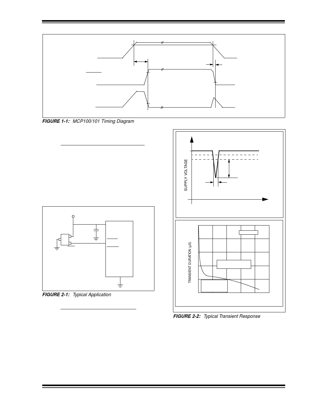
2.2 Negative Going VDD Transients
Many system designers implementing POR circuits are
concerned about the minimum pulse width required to
cause a reset. Figure 2-2 shows typical transient dura-
tion vs. reset comparator overdrive for which the
MCP100/101 will not generate a reset pulse. It shows
that the farther below the trip point the transient pulse
goes, the duration of the pulse required to cause a
reset gets shorter. A 0.1 µF bypass cap mounted as
close as possible to the VDD pin provides additional
transient immunity.
5V
TRANSIENT
DURATION
0
0
VTRIPMAX
VTRIPMIN
(VTRIPMIN - VDD)
TIME
10
TA = +25°C
8
6
Transients above the
4
curve will cause a reset
2
Transients below
the curve will NOT
cause a reset
0
0
1
2
3
4
5
VTRIP - VDD (V)
FIGURE 2-2: Typical Transient Response
© 1999 Microchip Technology Inc.
Preliminary
DS11187D-page 3
Share Link: 